D9068 | Operation and Installation Guide | 2.0 Installation
.
Bosch Security Systems, Inc. | 3/13 | F01U071094-07
2.0 Installation
You can install the D9068 up
to 500 ft
(152 m) from the FACP when
using a minimum of 18 AWG
wire.
Mount the D9068 indoors in a
dry location.
2.1 Mounting the Enclosure
The D9068 and its enclosure are shipped
together. Install the D9068 inside the
enclosure using the supplied mounting
hardware.
1. Remove the desired wire knockouts on
the enclosure. Refer to Figure 2.
Figure 2: Wire Knockout Locations
1 - Left exterior
2 - Right exterior
3 - Tamper switch holes (not used)
4 - Wire knockouts (5)
5 - Machine screw
6 - Self-tapping screw
7 - Front
2. Using the D9068 case as a template,
mark the mounting hole locations on
the desired wall.
3. Hang the case on the wall using the
appropriate installer-supplied
mounting screws (refer to Figure 3).
Figure 3: Mounting D9068 Case to Wall
1 - Position the enclosure with this
end up
2 - Enclosure mounting holes (2)
3 - Enclosure lances (4)
4 - D9068 mounting holes (3)
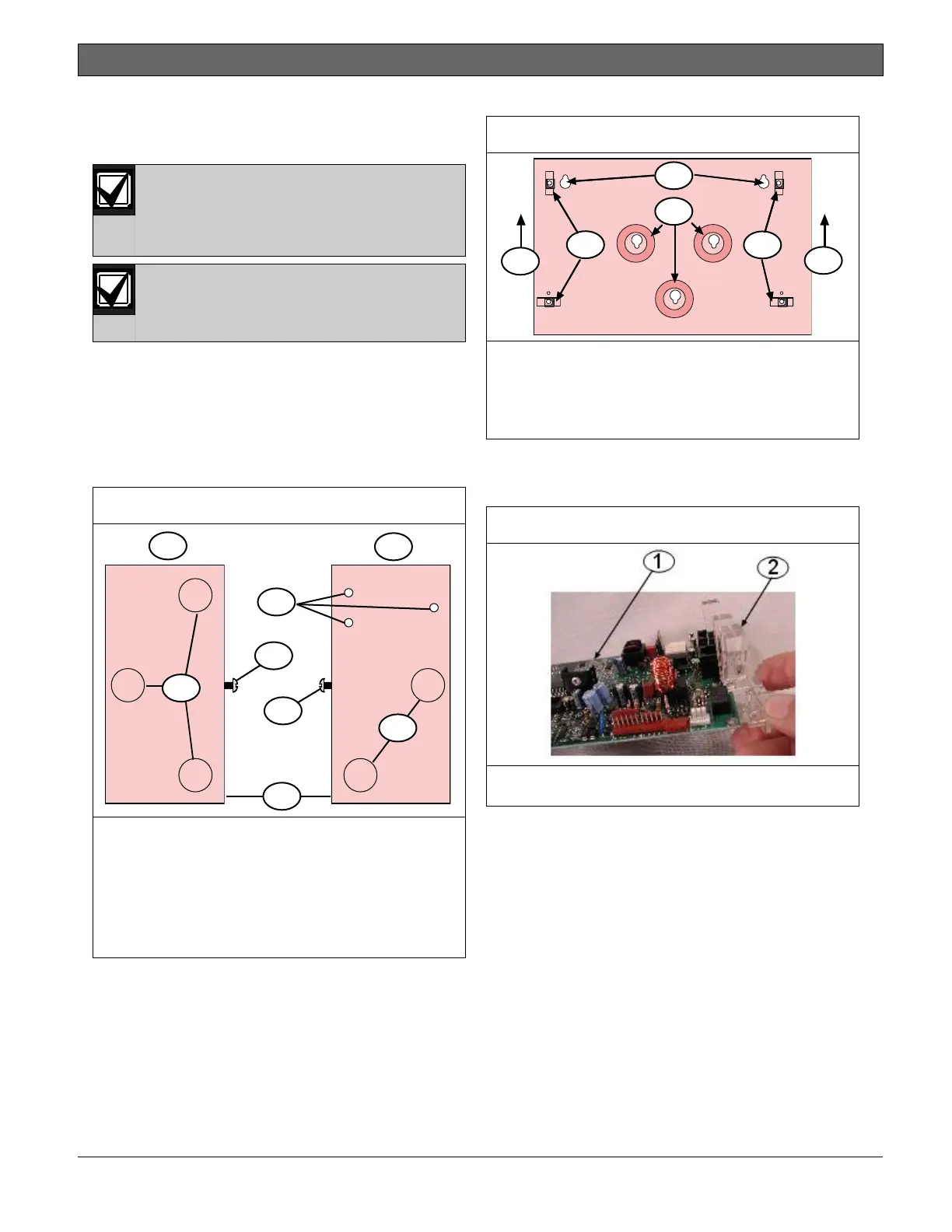
4. Slide the light pipe over the end of
the PCB (refer to Figure 4),
aligning it with the LEDs.
1 - D9068 PCB
2 - Light pipe
5. Mount the D9068 in the enclosure
using the supplied mounting screws
and mounting clips. Then attach the
ground wire from the FACP earth
ground to the earth ground terminal
on the DACT enclosure (refer to
Figure 5 on page 12).