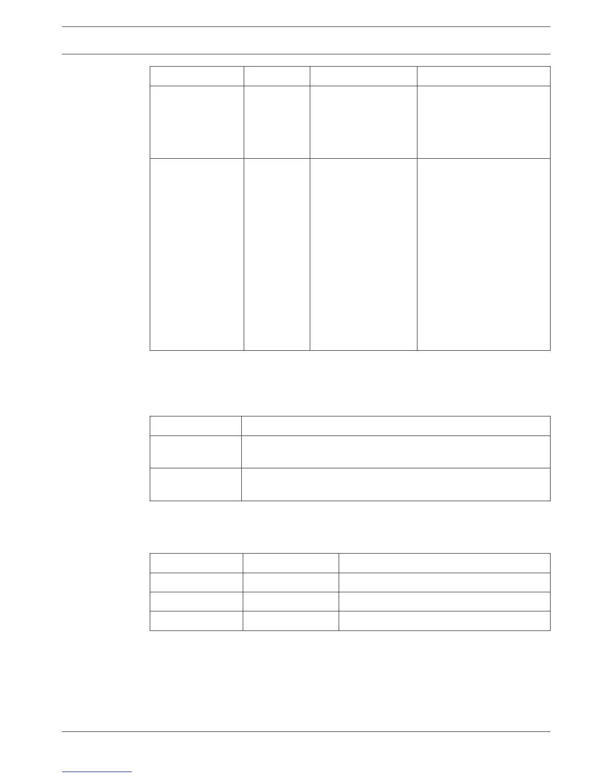
Menu item Parameter Value Description
8Ga Level Signal:
Input 1*
Input 2
Output 1
Output 2
Level:
-6 to 6 dB (0 dB*)
-6 to 6 dB (0 dB*)
-24 to 6 dB (0 dB*)
-24 to 6 dB (0 dB*)
The nominal levels of the
audio inputs and the audio
outputs of the central control
unit.
8Gb Routing I/O 2 --- Multi slave mode:
– Recorder*
– Delegate Ldspkr
– Local floor
– Insertion or Int.
Floor insert
Stand alone, Single,
Multi Master Mode:
– Recorder*
– Delegate Ldspkr
– Mix-Minus
– Insertion, Int. Floor
insert or Insertion
no AGC
The audio routing mode of
the central control unit.
Refer to Audio I/O routing,
page 16.
Table 7.9: Audio I/O sub-menu (* = default)
Camera control
Use the menu item in the 8H Camera Cntrl sub-menu to select the type of connected camera
system.
Value
Description
Autodome* The central control unit sends the camera control signal to a Bosch
Autodome (Baudrate 9.6 K).
Allegiant The central control unit sends the camera control signal to a Bosch
Allegiant (Baudrate 19.2 K).
Table 7.10: Camera control sub-menu values (* = default)
IP address
Use the menu items in the 8I IP Address sub-menu to set the IP address.
Menu item
Value Description
8Ia Address 192.168.0.100 * Sets the TCP/IP address.
8Ib Subnet Mask 255.255.255.0 * Sets the TCP/IP subnet mask.
8Ic Def. Gateway 0.0.0.0 * Sets the TCP/IP default gateway.
Table 7.11: IP Address sub-menu (* = default)
CCU mode
Use the 8J CCU Mode sub-menu item to set the mode of the central control unit.
Conference System
Configuration | en 187
Bosch Security Systems B.V. Operation Manual 2013.11 | V2.0 | DCN-NG_OM_V4.x





 To Next Page