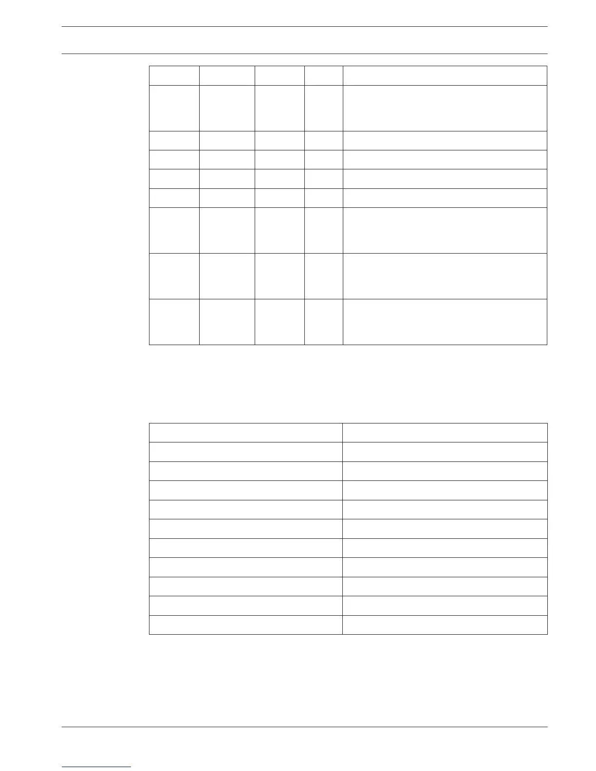
Address S8-6 S8-7 S8-8 Description
248 0 0 0 Numeric display (refer to DCN-DDB Data
Distribution Board, page 255 > Numeric
display)
249 1 0 0 Reserved
250 0 1 0 Reserved
251 1 1 0 Status display (e.g. synoptic display)
252 0 0 1 Reserved
253 1 0 1 Speak slowly signaling (refer to DCN-DDB Data
Distribution Board, page 62 > Speak slowly
signaling)
254 0 1 1 Help signaling (interpreter booth 1 to 16, refer
to DCN-DDB Data Distribution Board, page 62 >
Help signaling)
255 1 1 1 Help signaling (interpreter booth 17 to 31,
refer to DCN-DDB Data Distribution Board, page
62 > Help signaling)
Table 7.45: Addresses
Remote de-init switch
You can erase the address of the data distribution board from a remote site with connector
X77 (refer to DCN-DDB Data Distribution Board, page 62). This 10-pole connector has
connections for a de-init switch and a de-init LED.
Pin
Signal
1 +5 V
2 Init
3 Initialisation LED, anode
4 Initialisation LED, cathode
5 Not connected
6 Not connected
7 Not connected
8 Not connected
9 Not connected
10 Not connected
Table 7.46: X77 remote initialization connector
The remote de-init switch must be connected between pins 1 and 2. The de-init LED must be
connected between pins 3 and 4.
Conference System
Configuration | en 229
Bosch Security Systems B.V. Operation Manual 2013.11 | V2.0 | DCN-NG_OM_V4.x






 To Next Page