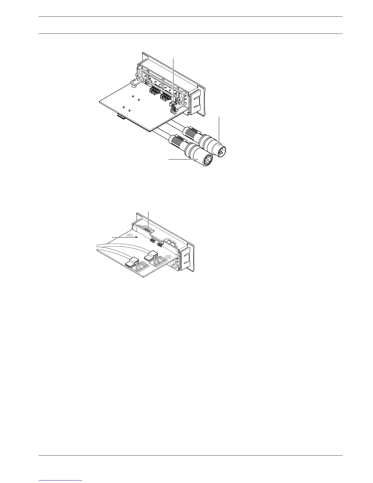
Figure 3.46: Bottom (all types)
1. Condition LED - Shows the condition of the voting unit.
2. Voting buttons - Operate the voting panel. Each button has a LED that shows the
condition of the button.
3. De-init switch - Erases the address of the voting unit. All LEDs on the voting unit come on
when the voting unit has no address.
4. DCN cable - Connects the voting unit to the DCN.
5. DCN socket - Makes a loop-through in the DCN with the voting unit.
6. External contact plug - Connects the voting unit to an external contact.
7. Solder spot - Configures the external contact plug.
The following sections give more information about the mentioned subject:
– Installation: DCN-Flush mounted products, page 103.
– Connection: DCN-FVU Voting Unit, page 141.
– Operation: DCN-FVU Voting Unit, page 251.
– Technical Data: DCN-FVU Voting Unit, page 284.
Conference System
System Overview | en 47
Bosch Security Systems B.V. Operation Manual 2013.11 | V2.0 | DCN-NG_OM_V4.x