2. Click ‘OK’ when done.
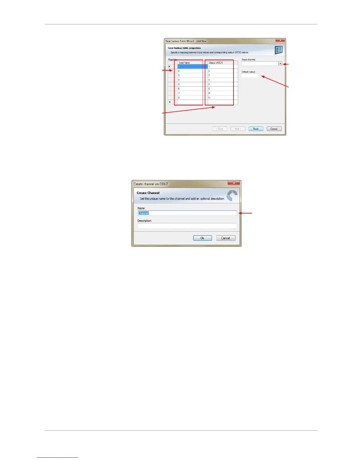
The ‘Create channel on DDU 8’ window appears.
3. Enter the name and an optional description of the translated ASCII measure‐
ment channel.
4. Click ‘Ok’ when done.
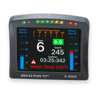
A graphic shows the connection between the input and output channels. The
measurement channel can now be used in the shift LED configuration.
Creating customized LED pattern
You can create your own LED pattern with an individually created condition. The
LEDs flash if the condition becomes true.
1. Click on the button ‘Add pattern’ in the display view. The LED pattern config‐
uration window appears.
8.3.3
Display Configuration | 8
Bosch Motorsport DDU S2 PLUS Manual 35 / 136