1 689 989 185 2018-03-24| Robert Bosch GmbH
42 | EPS 205 | Product descriptionen
3.6 Description of unit
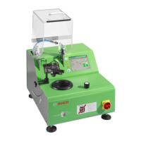
3.6.1 Front view
458881-11_Ko
1
2
3
4
5
6
7
8
9
10
Fig. 1: Front view
1 LCD with touch screen
2 Pen
3 PC connections
4 Connection for external extraction
5 Oil collector
6 Master switch (with emergency stop function)
7 Internal extraction controller
8 Oil level indicator
9 Guard with handle
10 High-pressure hose
3.6.2 Rear view
458881-101_K
o
1
2
Fig. 2: Rear view
1 Connector for three-phase current (400 V)
2 Compressed air connection
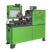
3.6.3 Components for testing
1
2
3
4
5
6
7
8
9
10
458881-12_K
O
Fig. 3: Components for testing
1 CRI Piezo return inlet
2 CRI Piezo return outlet
3 Clamp with clamping bolt for securing CRI/CRIN, CRI Piezo or
DHK/UI
4 Jet chamber
5 Injection chamber holder
6 Flushing drain
7 Clamping bolt for adjusting injection chamber holder height
8 Connection panel
9 Guard contact
10 Clamping bolt for adjusting clamp height
3.6.4 Connection panel
X20
458822-85
Fig. 4: Connection panel
1 Connecting cable for guard safety switch
2 Flushing connection for return quantity (CRI/CRIN)
*)
3 Test connection for return quantity (CRI/CRIN/CRI Piezo)
4 Test connection for injected fuel quantity (CRI/CRIN/CRI Piezo)
5 Flushing connection and test connection (DHK/UI);
flushing connection for injected fuel quantity (CRI/CRIN)
*)
6 Socket for CRI/CRIN/CRI Piezo
*)
The flushing connection for the return quantity and injected fuel
quantity (CRI/CRIN) has no function at present. It is intended for
possible subsequent extensions.
 Loading...