PRAESENSA System composition | en 43
Bosch Security Systems B.V. Installation manual 2019.11 | V1.00 |
The minimum installed battery capacity should be 100Ah to have a sufficiently low internal
impedance of the battery to accommodate peak current draw from connected amplifiers. The
maximum installed battery capacity is 230Ah to be able to charge the battery within the
permitted time according to EN54‑4 or similar standards.
The maximum current draw from the battery would be approximately 70A in alarm mode
without taking the losses of the battery cables, battery internal resistance, fuse and
connections into account. With the supplied battery cables and fuse, and assuming that the
internal resistance of the battery is 3.5mohm, the total series resistance is approximately
6mohm. The 70A current creates a loss of 0.42V across this resistance, so the 12V would
drop to 11.58V, making the supply voltage of the system, approximately 4% lower. Because all
PRAESENSA devices use DC/DC converters that take the required power regardless of small
deviations of the supply voltage, the 4% lower voltage is compensated by drawing 4% more
current, so approximately 73A. Because of this, the voltage drops a bit more and the current
increases a bit more again. This shows the high importance of keeping the series resistance of
the battery connections as low as possible. In quiescent conditions the current from the
battery is hardly 4A, worst case, so the cable losses are low (<0.1W), but at maximum output
power, the battery cable losses go up to 30W, causing the cables to warm up. Also see
section Battery and fuse, page 109.
5.4.6 Uninterruptable power supply size calculation
An alternative for the use of the multifunction power supply with built‑in battery charger and
converter, is to use the PRA-PSM48 to power PRAESENSA. This solution is not compliant to
EN54 and ISO7240, but still useful for non‑certified solutions. In this case the system
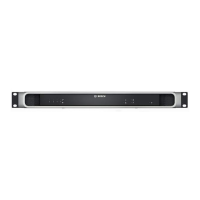
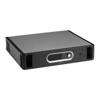
controller PRA-SCL and Ethernet switch PRA-ES8P2S can be powered from a PRA-PSM48
power supply module. The PRA-CSLD and PRA-CSLW can be powered via PoE from the PRA-
ES8P2S. The amplifiers PRA-AD604 and PRA-AD608 can also be powered from a PRA-PSM48,
not more than one amplifier per power supply. Also with this setup it is possible to have
battery backup power by using an uninterruptable power supply (UPS) to provide
uninterruptable mains power to the PRA-PSM48 power supply modules.
The required capacity of the UPS can be calculated in the same way as for the backup battery
of the multifunction power supply. Because the efficiency of the PRA-PSM48 power supply
modules is comparable to the efficiency of the DC/DC converters in the multifunction power
supply, take the data from the column “Power from battery [W]” in the table of Power
consumption, page 40. This is also the approximate amount of mains power that is taken by the
PRA-PSM48 , when it is powering the connected device or devices in the mode or
configuration that is specified in this table. To calculate the required battery capacity or
energy storage, the power consumption must be multiplied by the time that the devices are
powered in a specific mode, similar to what was done for the accurate battery size calculation
in Accurate battery size calculation, page 41. However, in this case the amplifiers cannot run in
snooze mode, but will run in idle mode while not being active. The snooze mode is only
available in combination with the multifunction power supply. In idle mode the power
consumption of the amplifiers is considerably higher than in snooze mode and this will have
an impact on the required backup power capacity of the UPS.
As an example, consider a voice alarm system that consists of the devices in the table below.
This small system has a system controller, one call station and three amplifiers; furthermore, it
has an Ethernet switch to connect and power the call station via PoE, because this system
doesn’t have a multifunction power supply. This system can be powered from four PRA-PSM48

 Loading...


