56 en | System controller | PRA-SCL/SCM/SCS PRAESENSA
2019.11 | V1.00 | Installation manual Bosch Security Systems B.V.
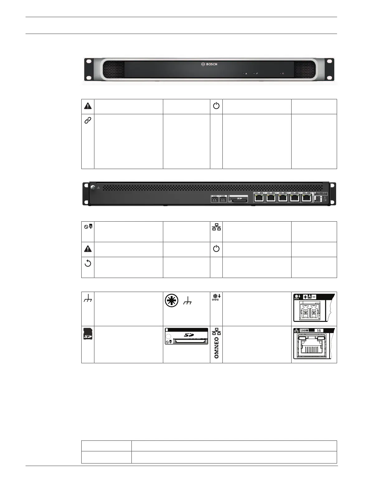
7.5 Indicators and connections
Front panel indicators
Device fault present Yellow Power on Green
Network link of backup
system controller to
duty system controller
present
Network link lost
Standby for redundancy
Green
Yellow
Blue *
Identification mode /
Indicator test
All LEDs blink
*Availability to be announced.
Rear panel indicators and controls
SD card busy; do not
remove
Green 100Mbps network
1Gbps network
Yellow
Green
Device fault present Yellow Power on Green
Device reset (to factory
default)
Button Identification mode /
Indicator test
All LEDs blink
Rear panel connections
Chassis ground 24 to 48VDC input A‑B
Memory card Network port 1‑5
7.6 Installation
The device can be connected everywhere within the PRAESENSA system. If required, refer to:
System introduction, page 13.
The device is designed to be installed in a 19"‑rack/cabinet. Refer to: Mounting the 19"-rack
devices, page 20.
7.6.1 Parts included
The box contains the following parts:
Quantity Component
1 System controller