5
System Controls
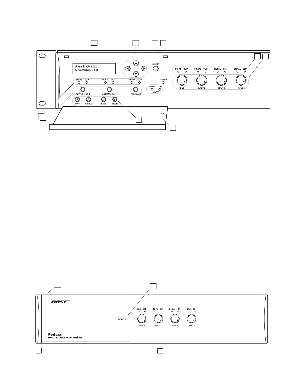
1 - LCD panel - Displays menu selection for
configuring and viewing system settings.
2 - Directional buttons - Navigate system
menus and setting options as shown on the
LCD.
3 - Select button - Confirms selections and
settings in the system menus.
4 - Power LED - Blue light indicates the
system is on. No light when it is off.
5 - Signal and Clip LEDs - Show signal
states for OUPUT 1, OUTPUT 2, PAGE and
DIRECT.
Signal Unlit = No signal
Clip Unlit = No clipping
Signal Green = Signal present
Clip Red = Clipping
6 - Gain knobs - Adjust gain for OUTPUT 1,
OUTPUT 2 and PAGE.
Hardware Description
7 - Bass and Treble knobs - Adjust tonal
balance for OUTPUT 1 and OUTPUT 2.
Control Compartment
8 - Enclosure Door - Conceals system
controls.
Input Controls
9 - SIGNAL and CLIP LEDs - Show signal
states for Inputs 1 - 4.
Signal Unlit = No signal
Clip Unlit = No clipping
Signal Green = Signal present
Clip Red = Clipping
10 - Gain knobs - Adjust gain for INPUT 1 -
INPUT 4.
Front panel with open compartment
Front panel with compartment closed
1
2
3
4
5
6
8
9
10
7
1 Latch location – Provides access to system controls. 2 Power status window – Reveals Power LED.
2
1