54
DISASSEMBLY PROCEDURES
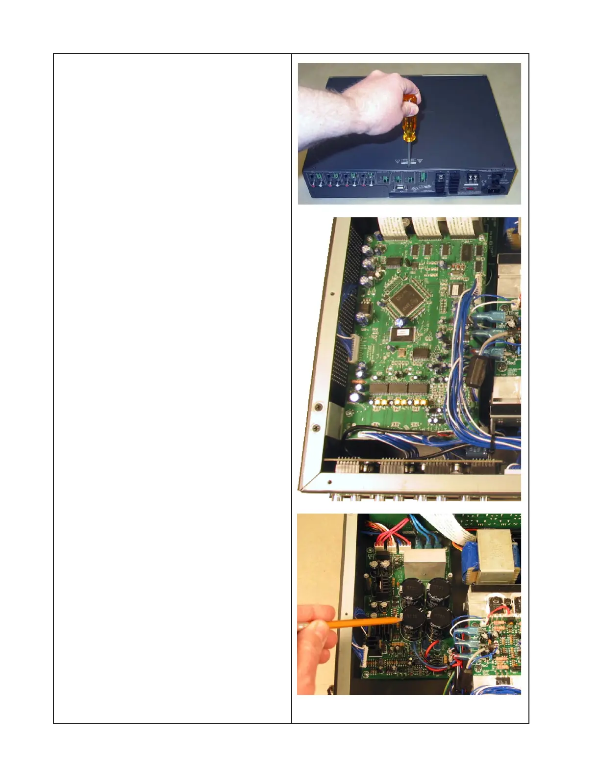
1. Top Cover Removal
1.1 Using a Phillips-head screwdriver,
remove the eight screws that secure the top
cover to the chassis. Lift off the top cover.
2. Digital Signal Processor (DSP)
PCB Removal
2.1 Perform procedure 1.
2.2 Unplug the three ribbon cables from the
front of the board at connectors CN08B,
CN09B and CN07B.
2.3 Unplug the wiring harnesses at connec-
tors CN13B, CN11B, CN10B, CN14B,
CN06B, CN05B, CN04B, CN03B, CN02B,
CN01B and CN12B.
2.4 Using a Phillips-head screwdriver,
remove the five screws that secure the
board to the chassis. Lift out the board.
3. Power Supply (PSU) PCB Removal
3.1 Perform procedure 2.
3.2 Unplug the two blue wires from connec-
tors JP601 and JP603. Disconnect the black
wire from connector JP602.
3.3 Unplug the wiring harnesses from con-
nectors CN16B, CN17B and CN601.
Re-assembly Note: Be sure to connect the
correct wiring harness to the correct connec-
tors at CN16B and CN601. Both connectors
are identical and damage to the unit could
result if they are plugged into the wrong
connector.