55
DISASSEMBLY PROCEDURES
3.4 Unplug the wiring harnesses at CN15A,
the fan connector and the NTC TH611.
3.5 Unplug the red, black and blue wires
from JP604A, JP605A and JP606A.
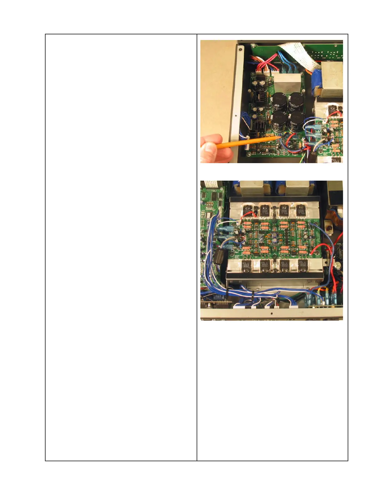
3.6 Located in the middle of the four large
electrolytic capacitors are three wires that
are soldered to the board, two black and
one green. Follow these wires over to the
SPKR PCB. Make a note of where they are
connected to the board and unplug them.
3.7 Using a Phillips-head screwdriver,
remove the five screws that secure the PSU
PCB to the chassis. Lift out the PCB.
4. Amplifier PCB Removal
4.1 Perform procedure 1.
4.2 Unplug the Red, Blue and Black Faston
connectors from the amplifier PCB. These
wires run up from the PSU PCB, located
under the DSP board.
4.3 Unplug the audio input cable from the
DSP PCB at CN06B. Unplug the wiring
harness from connector CN501.
4.4 At the other end of the board, follow the
red and blue wires to the SPKR PCB. Make
a note of where they are connected and
unplug these wires from the board.
4.5 Using a Phillips-head screwdriver,
remove the eight screws that secure the
output transistors to the heatsink.
4.6 Remove the three screws that secure
Q515, Q516 and thermistor TH611 to the
heatsink.
Reassembly Note: Be sure to retain the
transistor and thermistor retaining clips as
well as the mica insulators for re-use.
4.7 Remove the four screws that secure the
amplifier PCB to the heatsink. Lift off the
PCB.
 Loading...


