62
TEST PROCEDURES
Test Setup
AC power must be applied to the product variants as follows:
• DXA 2120 amplifiers with part number 294962-1, use 120VAC (+10/-1%), 60Hz
• DXA 2120 amplifiers with part numbers 294962-2, -4, and -5, use 240VAC (+10/-1%), 50Hz
• DXA 2120 amplifiers with part number 294962-3, use 100VAC (+10/-1%), 50Hz
Required Test Equipment
• Audio Signal Generator
• Oscilloscope
• Distortion Meter
• DC Power Supply capable of a 30V @ 2A output level
• Qty 2 - DXA-2120 Wallplates, PC: 041967
Test Conditions
• All AC audio measurements must be band limited from 22Hz to 22kHz
• All balanced line inputs must be terminated with 50 ohms
• All balanced mic inputs must be terminated with 150 ohms
• Line level output must be terminated with 400 ohms
• All amplifier outputs must be terminated with appropriate resistor values. See below.
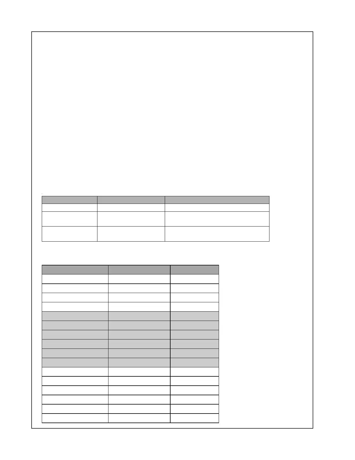
Standard test control positions
Set the unit under test controls to the positions listed in the table below.
Output Name Load Required Note
4 Ohm Output 4 Ohms @ 200W
70.7 Volt Output 49 Ohms @ 100W Jumper must be installed between
4 Ohm and Xfmr In
100 Volt Output 98 Ohms @ 100W Jumper must be installed between
4 Ohm and Xfmr In
Control Name Reference Designator Default Setting
Input 1 Trim VR401 Pot Fully CCW
Input 2 Trim VR402 Pot Fully CCW
Input 3 Trim VR403 Pot Fully CCW
Input 3 Trim VR404 Pot Fully CCW
Output 1 Trim VR405 Pot Fully CCW
Output 2 Trim VR406 Pot Fully CCW
Output 1 Treb VR409 Pot Centered (0dB)
Output 2 Treb VR411 Pot Centered (0dB)
Output 1 Bass VR408 Pot Centered (0dB)
Output 2 Bass VR410 Pot Centered (0dB)
Page Input Trim VR407 Pot Fully CCW
Input 1 Mic/Line Switch SW101 switch Line
Input 2 Mic/Line Switch SW102 switch Line
Input 3 Mic/Line Switch SW103 switch Line
Input 4 Mic/Line Switch SW104 switch Line
Power Switch Off

 Loading...