65
TEST PROCEDURES
2.2 Verify that you can make the following changes to the unit’s setup by pressing the RIGHT,
SELECT and UP keys respectively: You should be able to set the input gain, enable/mute the
outputs, and select the inputs. Repeat pressing the same key to get back to the original state.
2.2.1 Input Gain Setting
2.2.2 Output Enable/Mute
2.2.3 Input Select
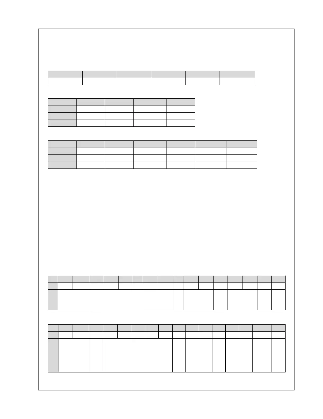
2.3 LCD Display Line 2 tests
With the unit under test in test mode, rotate the controls listed in the tables below and verify
that you get the correct information on line 2 of the display, i.e. that the values on the screen
go from 00 to FF for Input Knob 1.
Display on Line 2, LCD (2 lines x16 characters)
Because the knob values (00~FF) and the Version ID for the DSP software cannot be displayed
on one line, this information is organized into 4 groups: A, B, C, and D. Only one group at a
time can be displayed on line 2 of the LCD display. At the end of the line the letter A, B, C or D
indicates which group of information is being displayed. You can switch between groups by
pressing the DOWN key on the front panel. See the format for line 2 in the tables below:
Group A
Group B
1 2 3 4 5 6
-10 dB -20 dB -30 dB -40 dB -50 dB Mute
1 2 3 4
Out1
On Mute Mute On
Out2
Mute On Mute On
Aux
Mute Mute On On
1 2 3 4 5 6
Out1
Input 1 Input 2 Input 3 Input 4 Page In Direct In
Out2
Input 1 Input 2 Input 3 Input 4 Page In Direct In
Aux
Input 1 Input 2 Input 3 Input 4 Page In Direct In
1 2 3 4 5 6 7 8 9 10 11 12 13 14 15 16
1
2
Input 1
Knob
(00~FF)
Input 2
Knob
(00~FF)
Input 3
Knob
(00~FF)
Input 4
Knob
(00~FF)
Page In
Knob
(00~FF)
A
1 2 3 4 5 6 7 8 9 10 11 12 13 14 15 16
1
2
Output 1
Vol Knob
(00~FF)
Output 2
Vol
Knob
(00~FF)
Output
1
Bass
Knob
(00~FF)
Output
1
Treb
Knob
(00~FF)
Output
2
Bass
Knob
(00~FF)
B

 Loading...