69
TEST PROCEDURES
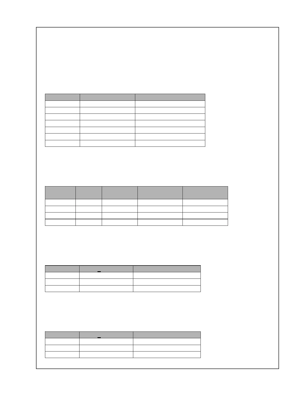
Output Connector Noise (30 Hz – 20 kHz)
Out1 pin 1 100V barrier -50 dBV
Out1 pin 2 70V barrier -50 dBV
Out1 pin 4 4 ohm barrier -60 dBV
Out2 pin 1 100V barrier -50 dBV
Out2 pin 2 70V barrier -50 dBV
Out2 pin 4 4 ohm barrier -60 dBV
Auxout 3 pin EuroBlock -80 dBV
Inject at Level
(dBV)
Measure
Gain (± 1dB)
THD+N
(20-30 kHz)
Input 1 -20 Out1 26.5 dB < 1%
Input 2 -20 Out1 26.5 dB < 1%
Input 3 -20 Out2 26.5 dB < 1%
Input 4 -20 Out2 26.5 dB < 1%
3.10 +24VDC Back-up test
With an appropriate power supply (i.e. 30V @ 2A) connected to the battery back up terminals
disconnect the A.C. power cord and insure that the amplifier does not shut down. Also observe
that the “A” in space 10 of line 1 on the LCD changes to a “D”. Reconnect the A.C. power cord
and continue testing the amplifier.
3.11 Output Noise
With all inputs terminated and undriven, measure the following:
3.12 Output Gain and THD
Inject a 1kHz, -20dBV tone sequentially into Input1, Input2, Input3, and Input4. Measure gain
and distortion for each channel as listed in the table below.
3.13 Direct Input (Override)
Apply a 1 kHz, 0dBV input to the direct input. Hold the Direct In pin 4 open and verify that no
signal is present at Out1, Out2, and Auxout. Tie Direct In pin 4 to pin 3, and verify the following:
3.14 Page Input
Apply a 1 kHz, -50dBV input to the page input. Hold the Page In pin 4 open and verify that no
signal is present at Out1, Out2, and Auxout. Tie Page In pin 4 to pin 3, and verify the following:
Measure Gain (+ 1 dB) THD+N (30 Hz – 20 kHz)
Out1 pin 3 26.5 dBV < 1%
Out2 pin 3 26.5 dBV < 1%
AuxOut 0 dBV < 0.1%
Measure Gain (+ 1 dB) THD+N (30 Hz – 20 kHz)
Out1 pin 3 16.0 dBV < 1%
Out2 pin 3 16.0 dBV < 1%
AuxOut 0 dBV < 0.1%

 Loading...