70
TEST PROCEDURES
3.15 Default Settings
The amplifier control knobs and switches should be set to the default positions as stated in the
table below. The amplifier’s DSP settings should be reset to their default conditions through the
utility menu on the front display. If firmware has been reloaded as part of this test procedure
then the reset step can be skipped.
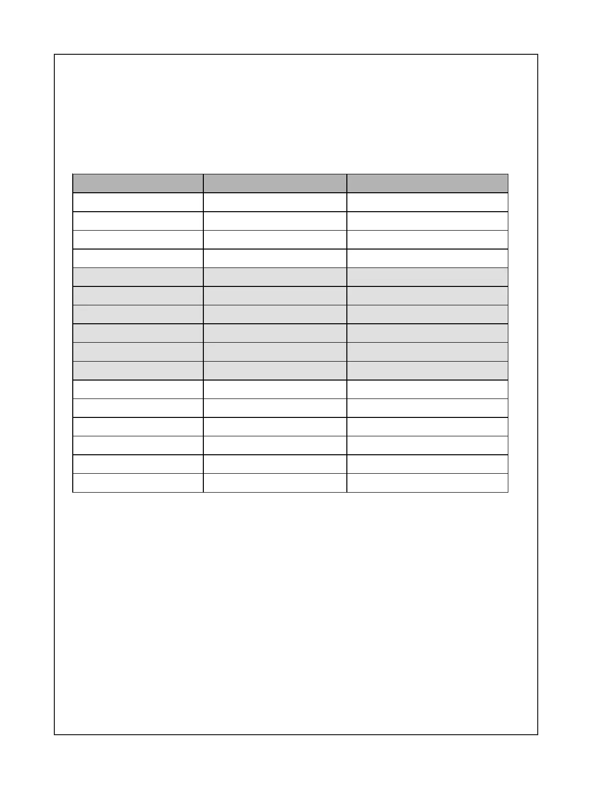
Standard test control positions
Control Name Reference Designator Default Setting
Input 1 Trim VR401 Pot Fully CCW
Input 2 Trim VR402 Pot Fully CCW
Input 3 Trim VR403 Pot Fully CCW
Input 3 Trim VR404 Pot Fully CCW
Output 1 Trim VR405 Pot Fully CCW
Output 2 Trim VR406 Pot Fully CCW
Output 1 Treb VR409 Pot Centered (0dB)
Output 2 Treb VR411 Pot Centered (0dB)
Output 1 Bass VR408 Pot Centered (0dB)
Output 2 Bass VR410 Pot Centered (0dB)
Page Input Trim VR407 Pot Fully CCW
Input 1 Mic/Line Switch SW101 switch Line
Input 2 Mic/Line Switch SW102 switch Line
Input 3 Mic/Line Switch SW103 switch Line
Input 4 Mic/Line Switch SW104 switch Line
Power Switch Off
 Loading...


