Service Manual 04/2010 Rev.B
111
Fig.251
Remove the spring, the washer and the ball
bearing (Fig.252).
Fig.252
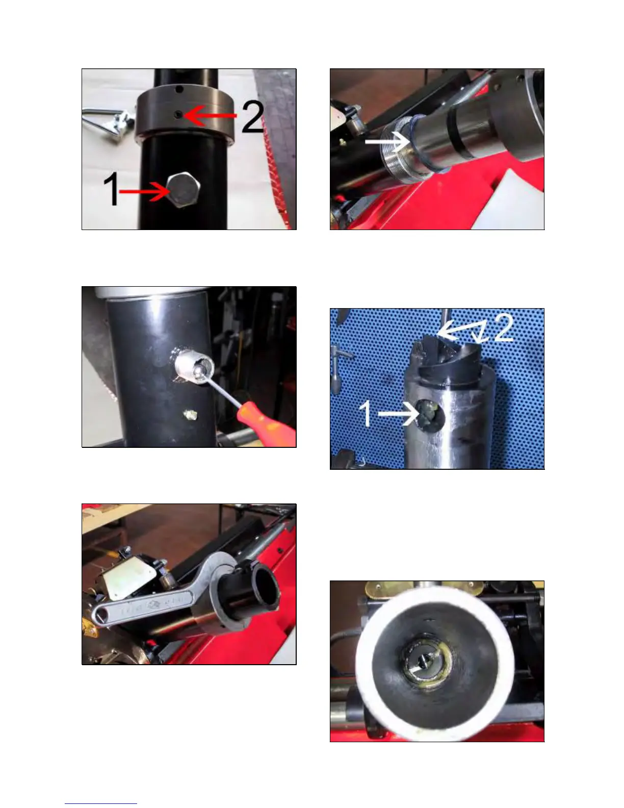
Remove the set screw #2 (Fig.251).
Remove the ring nut (Fig.253).
Fig.253
Pull out the rotor from the holder arm together
with ball bearings.
NOTE:
PAY ATTENTION TO THE ROTOR SHIM/S
SHOWN BY THE ARROW IN FIG.254.
Fig.254
Check if the hole #1 is too wide in case of
malfunction 1 (Fig.255).
Check if the rotor cam #2 is broken in case of
malfunction 2 (Fig.255).
Fig.255
Check if the rotor surface or the inner holder
arm are scratched in case of malfunction 3
(Fig.255 and 256).
IMPORTANT!
VERIFY IF THE LOWER CAMS OF FIG.249 ARE
FINE.
Fig.256