Service Manual 04/2010 Rev.B
56
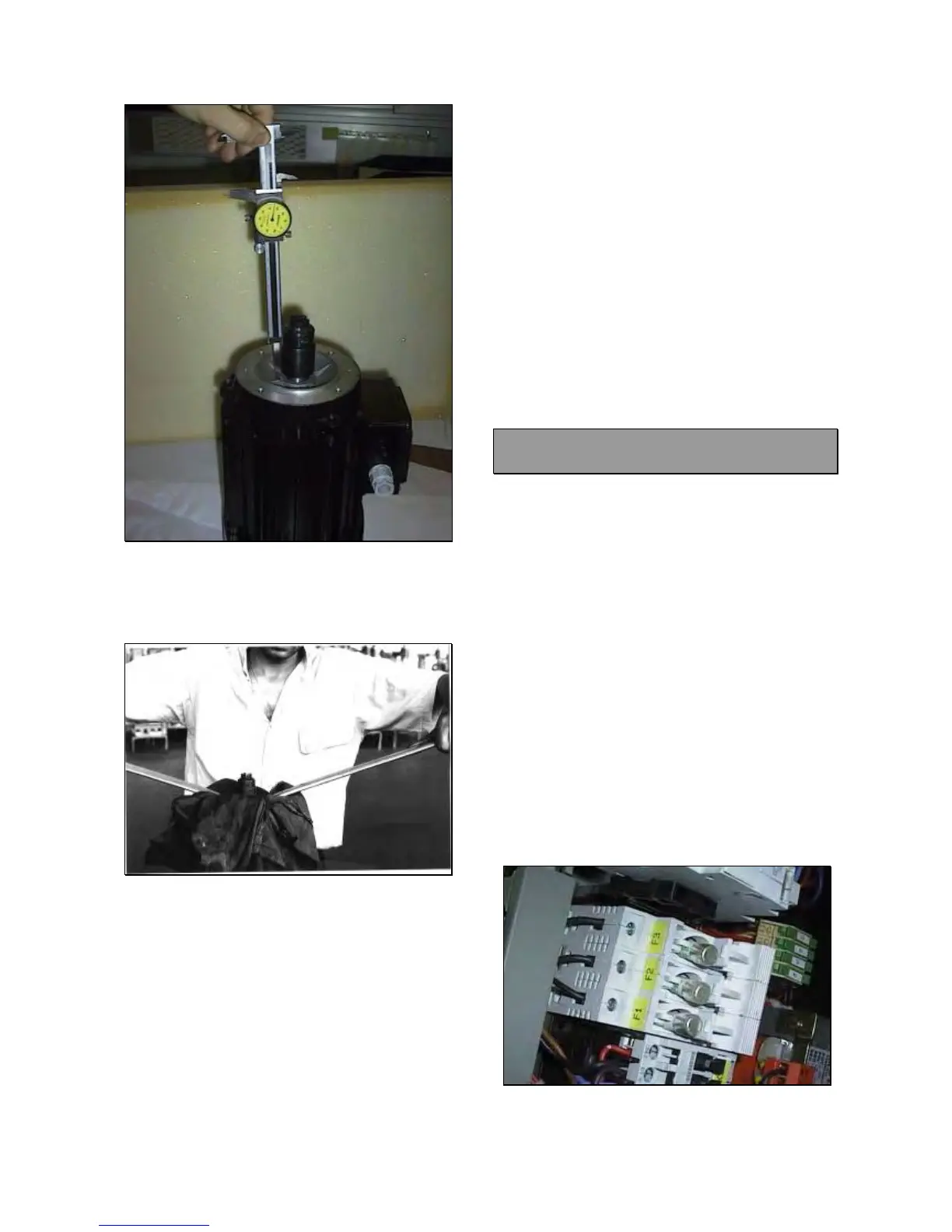
Fig.71
Lose the 3mm Allen screws of the joint and
remove it from the motor shaft by using two
levers (Fig.72).
Fig.72
Take the new motor.
Mount the joint following the distance
previously verified and lock it.
IMPORTANT!
A WRONG REGULATION OF THE JOINTS
WILL CAUSE HYDRAULIC PUMP DAMAGING
OR DAMAGING OF JOINTS THEMSELVES
WITH A CONSEGUENT NO HYDRAULIC
MOVEMENTS.
Mount the aluminium spacer: There is a little
hole in a face and this face must be mounted
downwards in order to show immediately if
there is an inner oil leaking.
Mount the motor on the hydraulic assy.
Connect the wires FIRMLY to motor terminals
following the voltage at which the machine is
supplied.
NOTE: Before connecting the wires ends, tighten
all terminals nuts.
Check the rotation way of the motor: If it is
wrong reverse only two motor wires otherwise
the chuck motor will turn wrongly.
Mount the motor terminals cover.
IMPORTANT: WHEN REMOUNTING THE
MOTOR TERMINALS COVER BE CAREFUL
NOT TO CRUSH WIRES.
5.6 FUSES F1, F2, F3: CHECK AND
REPLACEMENT
: 30’
: Multimeter
L : Defective fuse/s may cause the following
malfunction:
1. Chuck motor does not run at all.
TO CONTROL AND REPLACE THE FUSES:
Disconnect the machine from power supply.
Open the electric box (5.0).
Open the protection and remove the fuse
(Fig.73).
Verify if there is continuity between the ends
of each fuse.
If necessary, replace them with fuses of the
same value: 25A 500V.
IMPORTANT!
ON NON CE PROVED VERSIONS, THE CHUCK
MOTOR PROTECTION IS REPLACED BY A
CIRCUIT BREAKER (5.3).
Fig.73