Service Manual 04/2010 Rev.B
88
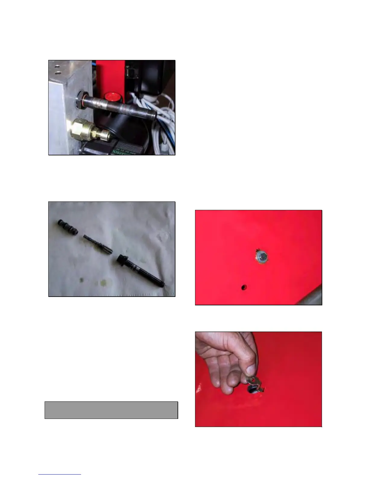
Remove the valve from aluminium block
(Fig.175)
Fig.175
Open the body valve by using 14mm end
wrench (Fig.176).
Clean very carefully all parts from slag and
dirty by air pressure.
Fig.176
Mount the body valve.
Install the valve on its aluminium block.
Install the O ring #6 (Fig.173).
Install the coil #5 (Fig.173).
Install the O rings #4 (Fig.173).
Install the coil #3 (Fig.173).
Install the O ring #2 (Fig. 173).
Tighten the plastic nut #1 (Fig.173).
Fit the coils connectors following the electric
diagram if the original position has been
forgotten.
Check if the machine works fine.
Mount the coil valve assy cover.
6.9 KING 5600 SADDLE CYLINDER:
CHECK AND REPLACEMENT
: 1h
: End wrenches 13, 19mm, Allen wrench of
8mm, 8 and 13mm tube type wrench, rubber
hammer, pliers, hydraulic oil container.
L : Defective cylinder may cause the following
malfunctions:
1. Oil leaking from welding.
2. Mechanical breakage.
NOTE: THE REPLACEMENT OF THE WHOLE
CYLINDER IS ONLY SUGGESTED IN CASE OF
MECHANICAL DEFECTS.
TO CHECK THE CYLINDER
Remove the hoses protection ( 6.1 Fig.129)
Switch the machine on.
Move to the left and to the right the saddle ‘till
end of strokes and verify if there are oil
leaking or mechanical breakages.
TO REPLACE THE CYLINDER ON KING 5600
Open the saddle cylinder ‘till end of stroke.
Remove the screw and the washers shown in
Fig.177.
Fig.177
Remove the plate locking (Fig.178)
Fig.178