Service Manual 04/2010 Rev.B
112
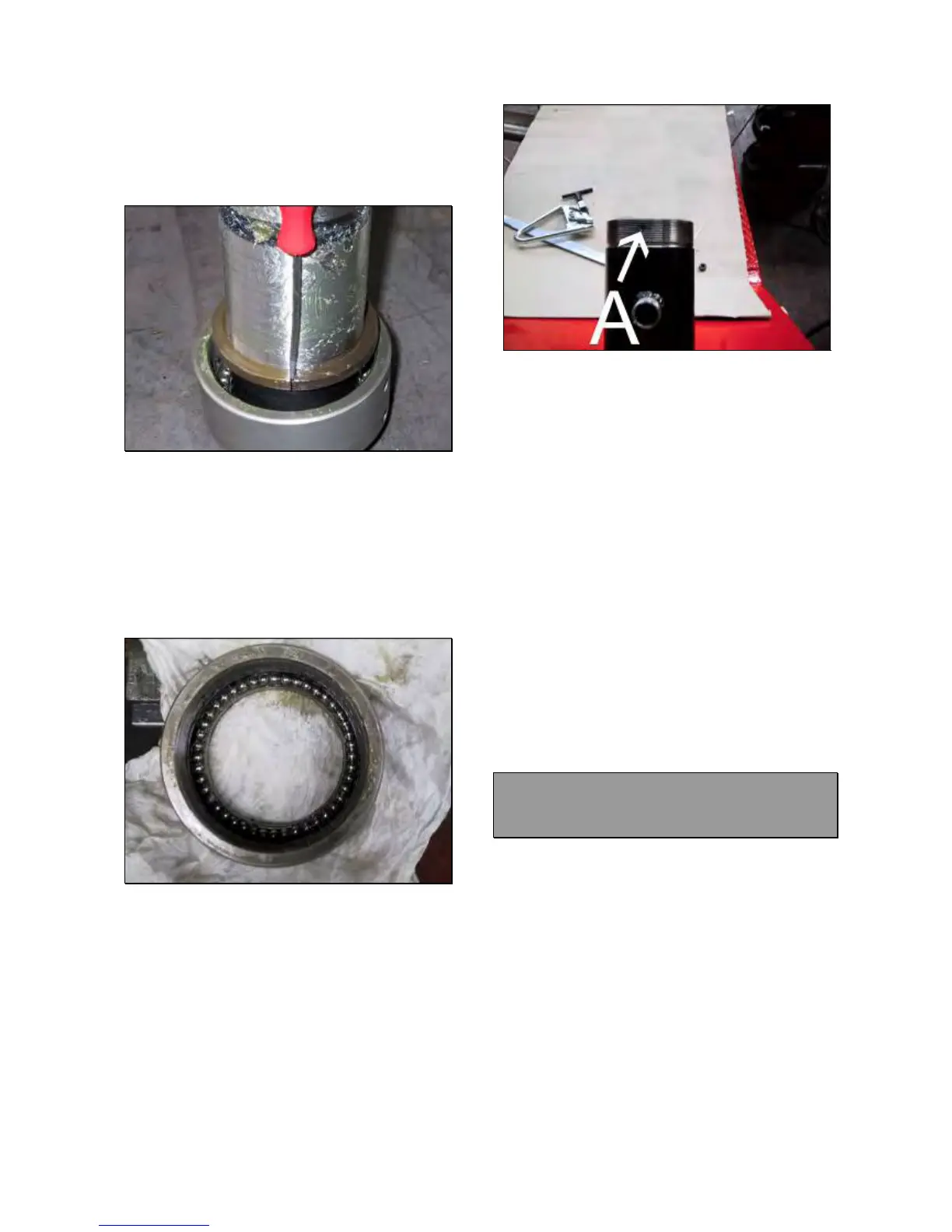
TO REPLACE THE ROBOTIC ROTOR:
Remove the shim of Fig.254 from rotor.
Remove the half ball bearings rings by using a
screwdriver (Fig.257).
Fig.257
NOTE:
PAY ATTENTION BECAUSE DUE TO THE
GREASE, SOME BALL BEARINGS COULD
REMAIN ATTACCHED TO THE HALF RINGS
AND THEY CAN DROP TO THE FLOOR.
Remove the ring nut with the ball bearings
and verify if there are all 44 balls (Fig.258).
Fig.258
Take the new rotor.
Insert the ring nut with the ball bearings.
Install the half rings.
Install the shim.
Grease the rotor.
Install the rotor on the holder arm by
tightening the ring nut.
IMPORTANT!
THE THREADED RING NUT HOLE MUST
MATCH WITH THAT ONE #A ON THE HOLDER
ARM THREAD (FIG.259).
Fig.259
Install the bearing ball, the washer (Fig.252)
and the ball bearing nut #1 (Fig.251).
Turn on the machine lower the hook to verify if
the rotor hole #1 (Fig.255) matches with
rotation proof pin.
Perform the control on both sides of the rotor.
If the rotation proof pin does not match with
the rotor hole, remove the rotor and take away
the shim of Fig.254. Then remount the rotor
following the same procedure.
Tighten the set screw #2 (Fig.251) by using
loctite.
Mount the tool.
Check if the machine works fine.
In case of malfunction 3, remove the
scratches from rotor and inner holder arm by
using file and sand paper.
Clean very accurately both parts.
Grease both parts.
Mount the rotor with washer following the
previous instruction.
Check if the machine works fine.
7.7 KING 5600R LOWER ROBOTIC
CAM AND SPRING: CHECK AND
REPLACEMENT
: 3h
: End wrenches of Allen wrench of 3 and
4mm, seeger pliers, steel and rubber hammer,
green loctite.
L : The robotic rotor may cause the following
malfunctions:
1. Incomplete mount dismount tool rotation.
2. Slow or locked mount dismount tool rotation.
IMPORTANT!
BEFORE STARTING WITH ROTOR
DISMOUNTING, BE SURE THAT RING NUT
AND ROTATIONAL BOLT ARE WELL
REGULATED 7.5 AND THE HYDRAULIC
PRESSURE IS CORRECT 6.4.
TO CHECK THE CAM: