Service Manual 04/2010 Rev.B
49
4.0 ELECTRIC FUNCTION
All King 5600 and 5600R truck tyre changers are
equipped by 3 phase motor only. Single phase
motors are not available on this style of machines.
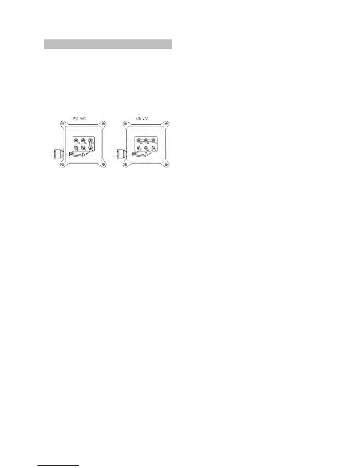
The machines can be wired at two different
voltages:
400 VAC (suitable for 360-415V range).
230 VAC (suitable for 200-250V range).
The voltage at which the machine is wired is
printed on the serial number plate and on a tag at
the end of the power cord.
The electric system of the machine is composed
by 3 circuits:
Power circuit.
Auxiliary circuit.
Protection circuit.
4.1 POWER CIRCUIT.
The power cord has 4 wires:
L1,L2,L3 = Phases
PE (yellow/green) = Ground
The main switch Q1 (Fig.16) controls the power to
the machine and it supplies the electric power to
the circuit breaker Q2 and to the 25A fuses
F1,F2,F3 (Fig.16).
The pump motor M (Fig.16) is controlled by the
circuit breaker Q2. In case of short circuit or
excessive heating, the circuit breaker cuts off the
power to the motor.
IMPORTANT!
The circuit breaker must be regulated
following the amperage printed on the label of
the pump motor.
On CE certified machines only, the circuit breaker
is controlled by a coil of minimum tension D1,D2
(Fig.16). It provides to cut off the power to the
pump motor in case, for any reason, there is no
power on the fuses F2,F3 (Fig.16).
The chuck motor M (Fig.17) rotation way is
controlled by the three polar meters K1 and K2
(Fig.17) while the inverter pole switch Q3 (Fig.17)
controlled the speed. The chuck motor is
protected by three 25A fuses F1,F2,F3 (Fig.17).
On machines for non CE market there is a further
circuit breaker Q3 (Fig.24) instead of the fuses
F1,F2,F3.
4.2 AUXILIARY CIRCUIT
The auxiliary circuit controls all movements of the
machine.
Two wires, U and V, connected to T1 and T2 of
the breaker circuit Q2 (Fig.17) supply high power
to the transformer T (Fig.17).
The transformer transforms the high power in
24VAC and 26VAC.
2 Fuses, F4 and F5, of 2A each one (Fig.17)
protect the main circuit of the transformer and 2
further fuses,F6 and F7, of 3.15A each one
protect the low power circuit.
The link converter (Fig.17) is supplied by
transformer and it transforms 26VAC in 24VDC to
be sent to the coil valves (Fig.18 and 19) for the
hydraulic movements.
The three polar meters K1 and K2 (Fig. 18), are
supplied by the transformer at 24VAC and they
control the rotation way of the chuck motor.
All movements of the machine are controlled by a
remote control where there are 4 switches (Fig.20
and 21):
S1 Controls the rotation way of chuck motor (2
pedals).
S2 Controls opening and closing of the chuck (2
position switch).
S3 Controls chuck arm and saddle movement (8
position switch, 4 position for Hoffmann Japan).
S6 Controls the tool holder arm movements (s
position switch on King 5600, 4 position switch on
King 5600R).
4.3 SAFETY CIRCUIT
All machines are equipped by a shut off switch S4
(Fig. 18) on the chuck arm to avoid injuries to
personnel or object laying on its pad.
The CE certified machines are equipped by an
emergency stop switch S5 (Fig. 18), which shut
off the 2 auxiliary circuit, 26VAC and 24VDC, in
case of emergency.