Service Manual 04/2010 Rev.B
68
FAIULURE #1 ALSO MAY BE CAUSED BE A
MECHANICAL MALFUNCTION OF THE SHUT
OFF SWITCH PROTECTION.
BEFORE STARTING WITH ANY ELECTRICAL
CONTROL VERIFY IF THE PROTECTION IS
WELL REGULATED AND IF IT MOVES UP AND
DOWN FREELY.
TO CONTROL THE CABLE:
Disconnect the machine from power supply.
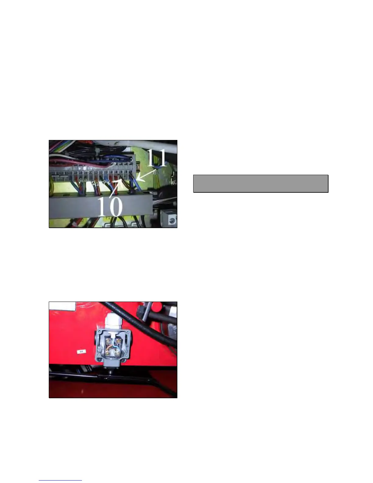
Open the electric box (5.0).
Disconnect the wires 10 and 11 from terminal
block into electric box (Fig.104).
Fig.104
Open the shut off switch S4 cover and
disconnect both wires (Fig.105).
Take a multimeter and select it in Ohm.
Position the multimeter probes on the ends of
same wire and verify if there is continuity (Ω =
0 ~ 0,3).
If there is not continuity the wire must be
replaced.
Fig.105
TO REPLACE THE CABLE:
Disconnect the machine from power supply.
Open the electric box (5.0).
Disconnect the wires 10 and 11 from terminal
block.
Open the shut off switch S4 cover and
disconnect both wires (Fig.105).
Release the strains cable relief on electric
box.
Take the defective cable away.
Insert the new cable.
Tighten the wires on the switch S4 and on the
terminals block FIRMLY.
Lock the switch S4 cover and tighten the
screws FIRMLY.
IMPORTANT: WHEN CLOSING THE
SWITCH DOOR BE CAREFUL NOT TO
CRUSH WIRES.
Tighten the strain cable relief leaving some
cable free (Fig.105).
5.19 SHUT OFF SWITCH S4: CHECK
AND REPLACEMENT
: 1h
: Small standard screwdriver, multimeter ,
pliers, end wrench 13mm, Allen wrench 4mm,
loctite.
L : Defective shut off switch may cause the
following malfunction:
3. The chuck arm does not come down.
5.0 Fuse F7 blows up.
IMPORTANT!
FAIULURE #1 ALSO MAY BE CAUSED BY A
MECHANICAL MALFUNCTION OF THE SHUT
OFF SWITCH SAFETY LEVER.
BEFORE STARTING WITH ANY ELECTRICAL
CONTROL VERIFY IF THE PROTECTION IS
WELL REGULATED AND IF IT MOVES UP AND
DOWN FREELY.
TO CONTROL THE SWITCH:
Disconnect the machine from power supply.
Open the electric box (5.1).
Disconnect the wires 10 and 11 from terminal
block.
Open the shut off switch S4 door and
disconnect both wires (Fig.105).
Take a multimeter and select it in Ohm.
Position the multimeter probes on the switch
terminals and verify if there is continuity (Ω =
0 ~ 0,3).
If there is not continuity the switch must be
replaced.
TO REPLACE THE SWITCH:
Release the strain cable relief on chuck arm.
Remove the defective switch.
Install the new switch.