Service Manual 04/2010 Rev.B
50
The three polar meters K1 and K2, are equipped
by a mechanical security (Fig.65) to avoid the
starting of both meters simultaneously saving the
motor from blowing up.
On Ce proved machined the chuck motor is also
equipped by a thermostat R1 connected to K1 and
K2 (Fig.18): in case of overheating it disconnects
K1 and K2 automatically.
When the chuck motor is cold the thermostat gets
closes and K1 and K2 are reactivated
automatically.
All King 5600R are also equipped by a safety
micro switch S7 on the Robotic assy that locks all
hydraulic movements, except the toolholder lifting
and lowering, whenever the toolholder hook is not
well clamped.
5.0 ACCESS TO ELECTRIC PARTS
BEFORE APPROACHING THE
ELECTRIC PARTS OF THE
MACHINE, DISCONNECT THE
MACHINE FROM ELECTRIC
SUPPLY.
Very often electric failures are only caused by
loosened wires or connectors not well fitted.
Therefore it is VERY IMPORTANT BEFORE
STARTING WITH ANY CONTROL AND/OR
REPLACEMENT VERIFY IF ALL WIRES AND
CONNECTORS ARE WELL FITTED.
To access to electric parts of the machine:
Fig.56
ELECTRIC BOX: Turn all switches off and
open the box by lifting the lever up (Fig.56).
Sometimes the opening may result difficult
because of door seal sticking.
When this happens the door can be easily
opened by pulling it with both hands from top
and bottom.
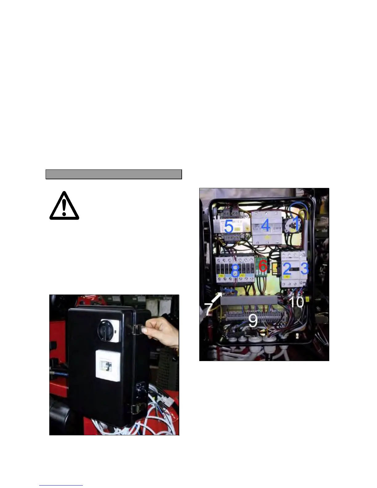
The electric box contains the following electric
components (Fig.57):
#1 Main switch Q1
#2 Circuit braker Q2
#3 Coil D1,D2
#4 Fuses F1,F2,F3
#5 Transformer T
#6 Fuses F4,F5,F6,F7
#7 Link converter
#8 Three polar meters K 1,K2
#9 Control wires terminal
#10 Inverter pole switch
Fig.57
PORTABLE CONTROL: Remove the 4
screws from the base and lift up the column
(Fig.58).