Service Manual 04/2010 Rev.B
72
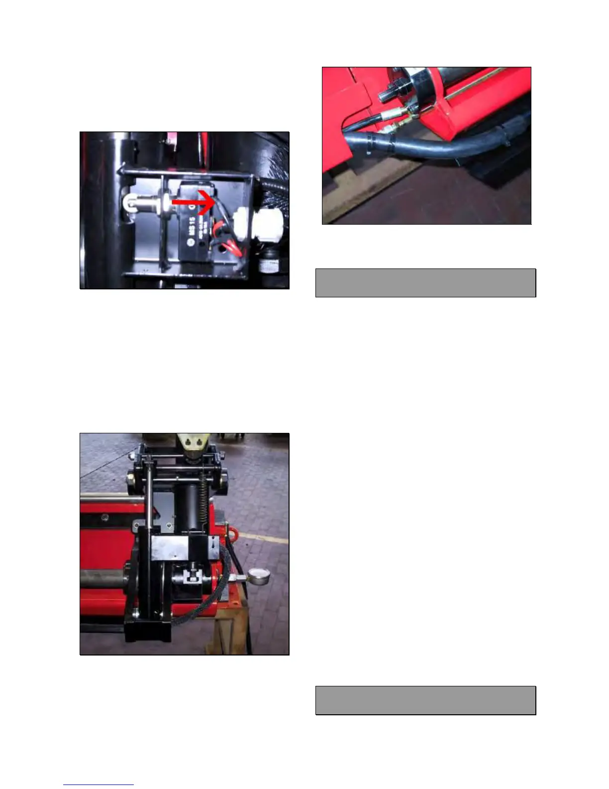
Lower all way down the tool holder ‘till to have
its cylinder at the end of the stroke: all function
of the machine should work normally. If not
move a little the switch by following the arrow
in Fig.119.
Fig.119
Tighten the cable strein relief.
Mount the switch cover and fit the hoses with
a clip hose (Fig.114).
IMPORTANT: WHEN FIXING THE SWITCH
COVER, BE CAREFUL NOT TO CRUSH
WIRES.
Move the tool holder ‘till end of the stroke and
leave some hoses free (Fig.120)
Fig.120
Lock the hoses on their protection and mount
the rubber tube (Fig.121)
Install the protection (Fig.115).
Mount the plastic spring around the hoses.
Fig.121
Check if the machine works fine.
5.22 ROBOTIC SAFETY SWITCH :
CHECK AND REPLACEMENT
: 1h
: Small standard and cross screwdrivers,
3mm allen wrench, 6mm end wrench, pliers,
multimeter.
L : Defective switch may cause the following
malfunction:
1. All hydraulic movements, except tool holder
lifting and lowering, do not work.
TO CONTROL THE SWITCH:
Switch the machine on.
Lower the tool holder arm and hook it.
Make sure to have the hook cylinder at the
end of stroke.
Turn off the machine and open the electric
box.
Disconnect the wires 20 and 21 from terminal
block (Fig.110).
Take the multimeter and select it in Ohm.
Verify if there is continuity between the wires
20 and 21.
If there is not continuity the switch must be
replaced.
IMPORTANT!
BEFORE STARTING WITH SWITCH
REPLACEMENT VERIFY IF IT IS WELL
REGULATED AND VERIFY IF THE WIRE IS
FINE.
TO REPLACE THE SWITCH:
Replace the switch following 5.21
5.23 COIL CONNECTOR CABLE:
CHECK AND REPLACEMENT