Service Manual 04/2010 Rev.B
71
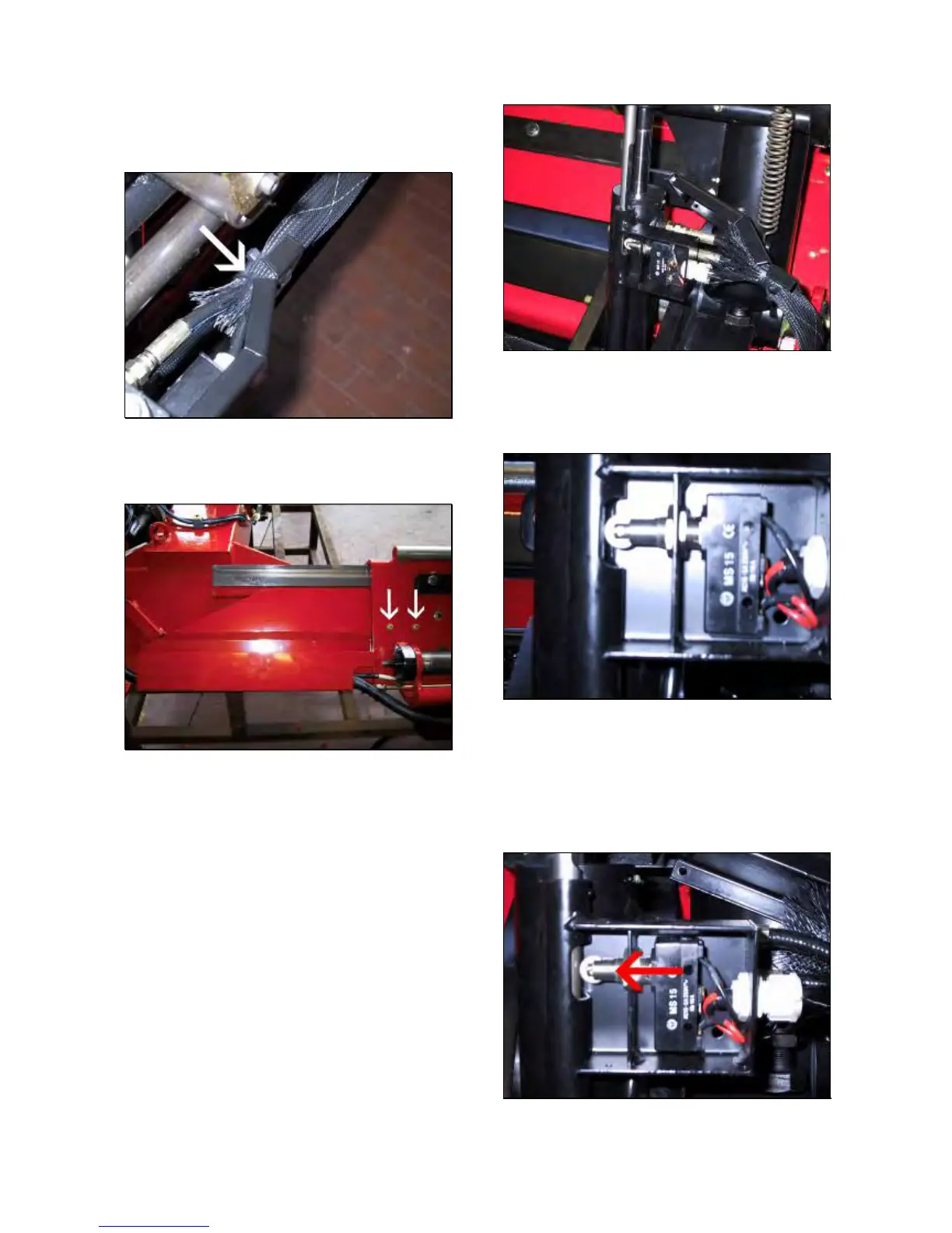
Disconnect the wires from the switch.
Cut the clip hoses and remove the switch
cover (Fig.114).
Fig.114
Remove the 2 bolts shown by the arrows and
take away the protection (Fig.115).
Fig.115
Remove all plastic protections.
Take away the defective cable.
Insert the new cable.
Connect the cable to the robotic switch.
Mount the switch on its support in order to
have all movements running.
Connect the cable to the terminal block 20
and 21 into the electric box.
Turn on the machine and open the saddle
until end of the stroke (Fig.115).
Lift up the tool holder ‘till to have the switch
wheel on the machined size of the safety rod
(Fig.116).
Fig.116
Regulate the switch in order to have its wheel
as closest as possible to the machined safety
rod but leaving it free (Fig.117)
Fig.117
Lock the switch nuts FIRMLY.
Lower the tool holder a little and check if all
movements are locked: If not decrease a little
the clearance between switch wheel and
machined safety rod by moving the switch as
shown by arrow (Fig.118).
Fig.118