Service Manual 04/2010 Rev.B
90
Mount the washers and the screw of Fig.177.
Open and close the cylinder to verify if it is
working fine.
Mount the oil hoses protection (6.1 Fig.129).
Make the hydraulic oil level (6.2).
6.10 KING 5600R SADDLE CYLINDER:
CHECK AND REPLACEMENT
:1h30’
: End wrenches 13,19 and 27mm, Allen
wrench of 8mm, 8 and 13mm tube type
wrenches, pliers, medium cross screwdriver,
steel and rubber hammer, pliers, hydraulic oil
container, loctite, sylicon.
L : Defective cylinder may cause the following
malfunctions:
1. Oil leaking from welding.
2. Mechanical breakage.
NOTE: THE REPLACEMENT OF THE WHOLE
CYLINDER IS ONLY SUGGESTED IN CASE OF
MECHANICAL DEFECTS.
TO CHECK THE CYLINDER:
Remove the cylinder protection (6.1
Fig.127)
Switch the machine on.
Move to the left and to the right the saddle ‘till
end of strokes and verify if there are oil
leaking or mechanical breakages.
TO REPLACE THE CYLINDER:
Close the saddle cylinder ‘till end of stroke.
Remove the hose plastic separators (Fig.184).
Fig.184
Turn on the machine.
Open the saddle ‘till end of stroke.
Turn off the machine.
Remove the screw and the washers shown in
6.9 Fig.177.
Remove the locking plate 6.9 Fig.178.
Remove the pin by using the tool for removal
of cylinder pin (Fig.185).
Fig.185
Turn on the machine.
Close the cylinder ‘till end of stroke.
Turn off the machine.
Remove the coil valve cover (5.23 Fig.122).
Press the coil valve to unload the hydraulic
pressure in the circuit 5.13 Fig.93).
Remove the hose protection 6.1 Fig.127.
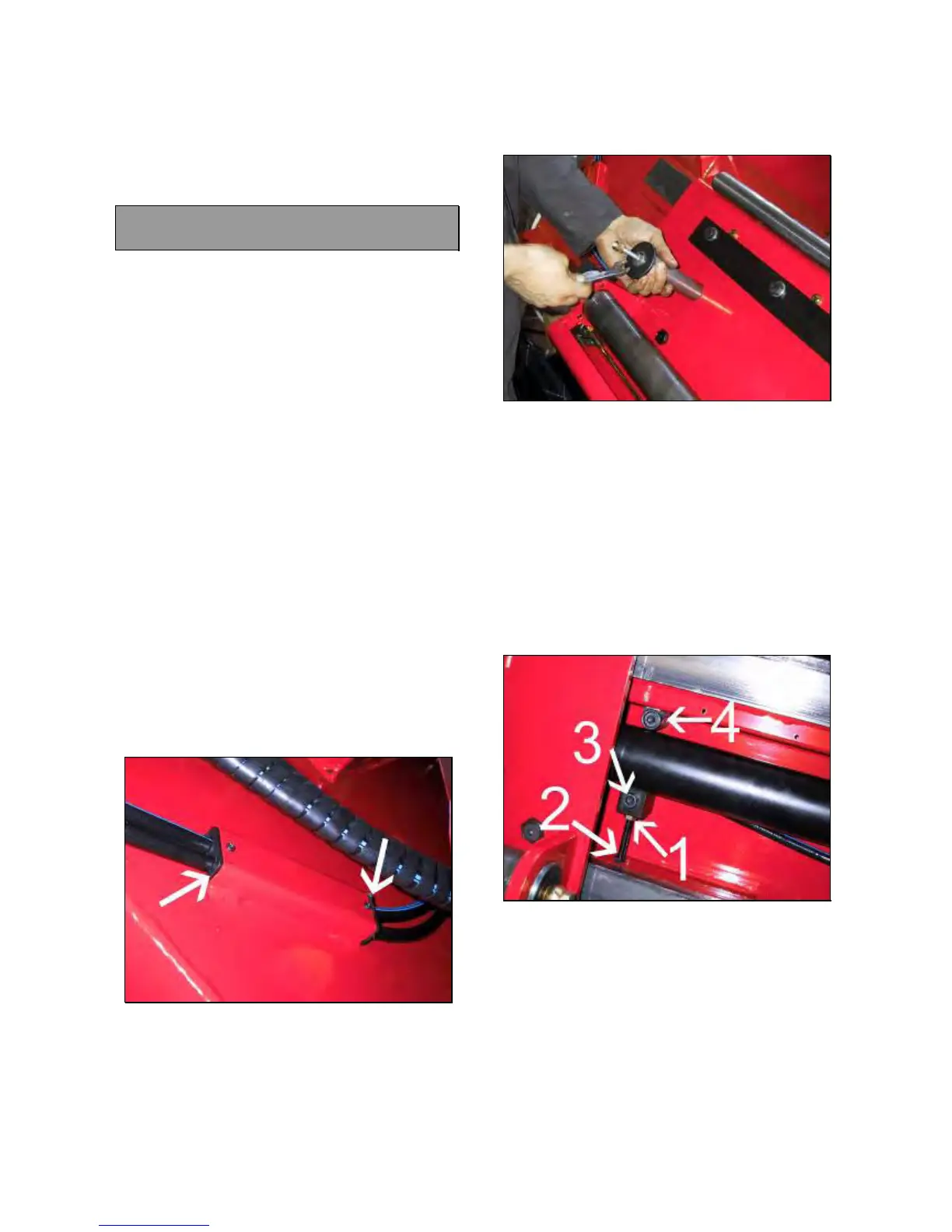
Loose the nut #1 (Fig.186).
Tighten the screw #2 ‘till have it free from the
cabinet (Fig.186).
Unscrew the screw #3 and #4 to remove the
cylinder supports (Fig.).
Fig.186
NOTE: VERY OFTEN THERE ARE ONE OR
MORE SHIMS BETWEEN SUPPORT #4
(FIG.186) AND CABINET. THESE SHIMS MUST
INSTALLED AGAIN DURING THE MOUNTING
OPERATION.
Remove the short oil hose from the hydraulic
assy.
Remove the oil hose #A (Fig.187)