Service Manual 04/2010 Rev.B
87
7. Mount both covers very carefully in order to
avoid damaging to the new seals.
8. Tighten the screws FIRMLY.
9. Take a couple of pliers and turn the pump
shaft: it must turn freely.
In case all seals and O ring will result fine, the
pump needs to be replaced.
Take a new pump and fit it on its support.
Tighten the pump bolts FIRMLY.
Take a couple of pliers and turn the pump
shaft: it must turn freely.
Mount the oil reservoir.
Take the oil previously saved in the cleaned
tank and put it into the reservoir.
Switch the machine on and check the
maximum hydraulic pressure.
Make the hydraulic oil level.
Remove the manometer and install the bolt
with two news copper washers.
Mount the hydraulic assy top cover.
6.8 COIL VALVE: CHECK AND
REPLACEMENT
: 30’ each one
: Small cross screwdriver, end wrenches
10,14 and 22mm, hydraulic oil container.
L : Defective coil valve may cause the following
malfunction:
1. Oil leaking.
2. One or more hydraulic movements start
themselves.
3. The chuck arm lowers itself (machine NON
CE PROVED ONLY).
4. One or more hydraulic movements do not
work.
5. Low chucking pressure.
TO CHECK THE COIL VALVE:
Remove the coil valve assy top cover.
Remove the coil connectors.
Switch the machine on: if a hydraulic
movement start it self, the coil valve needs to
be opened and cleaned.
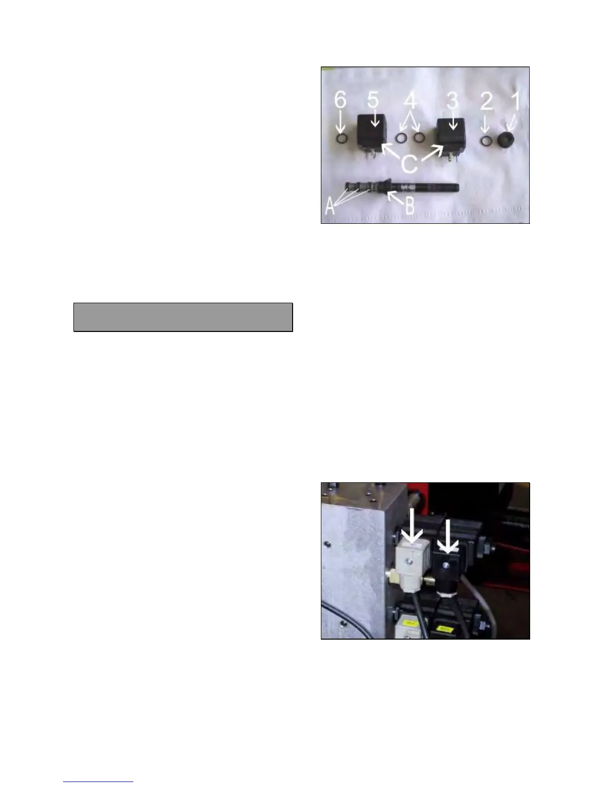
If the machine shows low hydraulic pressure
replace the 3 small “O” rings #A (Fig.173) by
following the instruction below reported..
If the there is an oil leaking between the valve
body and the aluminium block, the larger “O”
ring #B must be replaced (Fig.173) by
following the instruction below reported..
If there is an oil leaking through the valve
piston, replace the complete valve by
following the instruction below reported..
Fig.173
To verify the point 4, switch the machine on.
Press the coil valve correspondent to the
locked movement by screwdriver (5.13
Fig.93): if the machine works normally verify
coil connector cable 5.23 and portable
control cable 5.14 .
If 5.23 and 5.14 will be fine, the malfunction
is due to a defective coil #C (Fig.173).
TO CLEAN THE COIL VALVE:
IMPORTANT!
DO NOT DISMOUNT ANY COIL VALVE WITH
OPENED CHUCK CYLINDER AND LIFTED
CHUCK ARM.
Switch the machine off.
Press the coil valve by screwdriver to unload
the remaining pressure (5.13 Fig.93).
Remove the coils connectors shown by the
arrows (Fig.174).
Fig.174
Remove the plastic nut #1 (Fig.173).
Remove the O ring #2 (Fig. 173).
Remove the coil #3 (Fig.173).
Remove the O rings #4 (Fig.173).
Remove the coil #5 (Fig.173).
Remove the O ring #6 (Fig.173).