Service Manual 04/2010 Rev.B
113
Remove the rotor 7.6.
Verify if the cams are broken 7.5 (Fig.256).
TO CHECK THE SPRING:
Turn on the machine.
Lower the tool holder arm.
Turn off the machine.
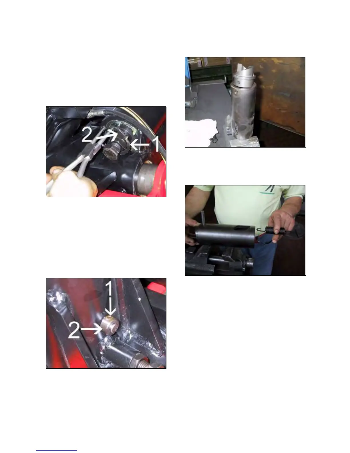
Remove the seeger ring #1 and take away the
cover #2 (Fig.260) without remove the screw.
Fig.260
If the spring is free, it is broken and it must be
replaced.
TO REPLACE THE CAM AND THE SPRING:
Turn on the machine and lift the tool holder.
Turn off the machine.
Remove the set screw #1 and take away the
stopper #2 (Fig.261)
Remove the pin #3 (Fig.269) from the arm.
Fig.261
Turn on the machine and lower the tool
holder.
Turn off the machine.
Push out from bottom to the top the cam assy.
Lock the cam assy on a vice and remove the
cam pin.
Replace the cam and/or the spring (Fig.262
and 263).
Fig.262
NOTE: THE OPENED END SPRING MUST
FITTED ON THE CAM PIN AS SHOWN IN
FIG.263.
Fig.263
Grease the cam assy and the holder arm.
Insert the cam assy into the holder arm.
IMPORTANT!
THE ASSY HAS TWO DIFFERENT WINDOWS
SIZES (FIG.264 AND 265): IT MUST BE
INSERTED INTO THE HOLDER ARM WITH THE
SMALL ONE TOWARD THE TOP (FIG.266).
 Loading...