Service Manual 04/2010 Rev.B
82
THE LITTLE HOLE ON THE FLANGE MUST
MATCH WITH THE LITTLE ON THE CHUCK
CYLINDER, OTHERWISE THE CYLINDER WILL
OPEN BUT IT WILL NOT CLOSE ANYMORE
Tighten two flange screws paying attention to
avoid the dropping of the shim.
Check if the chuck turns free by hand: if not
the shim is dropped and it must be placed
correctly.
Tighten the rest of the bolts very carefully by
using a dynamometric wrench regulated at
8Kgm (Fig.154).
Fig.154
Mount the anti rotational bolts #2 (Fig.150):
the small plate #4 must be left free.
Install the oil hoses
Install the manometer.
Switch the machine on and open the chuck
arms ‘till having the cylinder with maximum
pressure.
Keep the chuck cylinder quite opened for 10’.
After 10’ unlock the chuck cylinder pressure
unless close the arms and open it again ‘till
having maximum pressure again for further
10’.
Perform the above operation three times
IMPORTANT!
DO NOT TAKE CARE OF THE PRESSURE
SHOWN BY THE MANOMETER AFTER THE 1
ST
AND THE 2
ND
CONTROLS.
At the end of the third test the pressure shown
by the manometer should not be decreased
below than 140 Bar (2050PSI).
Remove the manometer and install the bolts
with a new copper washer.
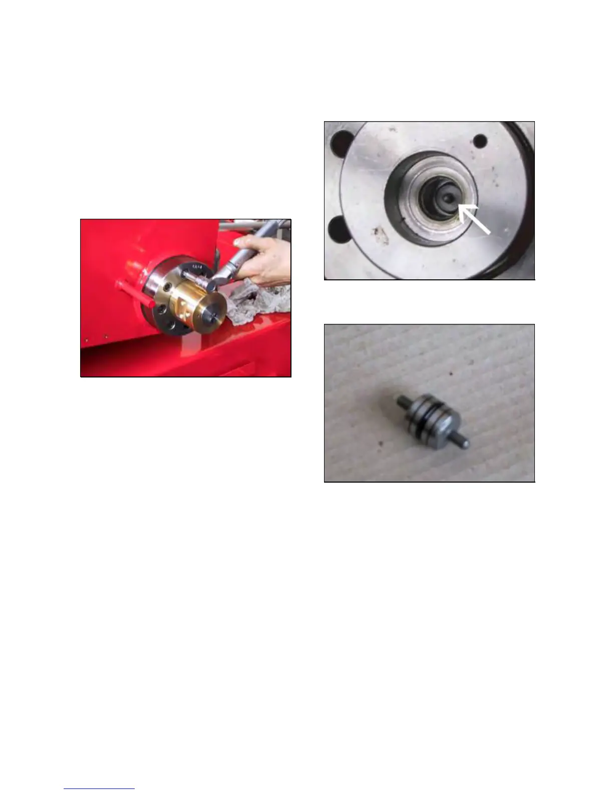
6.5.2 PISTON RELEASE LOCKING
VALVE “O” RING.
TO CONTROL AND REPLACE THE O RING:
Remove the locking valve from chuck cylinder
flange following the point1.
Remove the piston shown by the arrow in
picture 155.
Fig.155
Check if the piston O ring is fine (Fig.156)
Fig.156
Install the new O ring on the piston.
Clean very carefully the flange to avoid that
pieces of “O” ring get in the hydraulic oil
circuit.
Mount the piston into the flange.
Mount the rest of the parts by following the
point 1.
Check if the machine works fine.
6.5.3 REAR CYLINDER FLANGE
TO CHECK THE FLANGE:
Remove the manifold revolving assy from
cylinder following ( 6.5.1).
Remove the release piston from the flange (
6.5.2).
Verify if there excess of clearance between
piston and its side into the flange (Fig.157): if
there to much clearance the flange must be
replaced.
 Loading...