ENGLISH 50 / 78 CAP. 11 - REFRIGERANT FLUID CIRCUIT
CAP. 11 - REFRIGERANT FLUID CIRCUIT
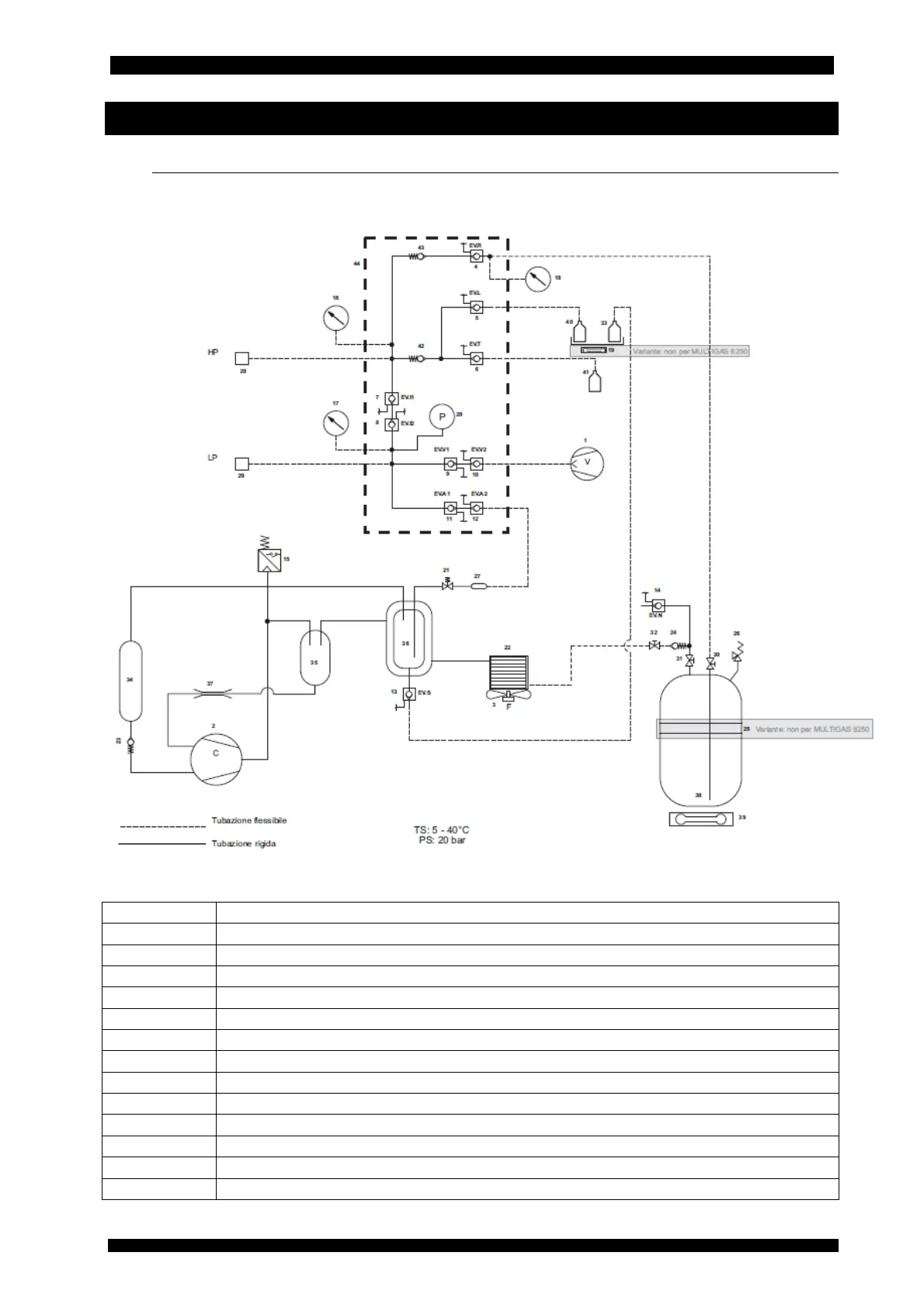
11.1 REFRIGERANT FLUID CIRCUIT
The chart of the refrigerant fluid circuit of MULTIGAS 8500 is reported as follows.
1 Vacuum pump
2 Compressor
3 Capacitor fan
4 Refrigerant charge solenoid valve
5 New oil injection solenoid valve
6 Tracer injection solenoid valve
7-8 Interception HP-LP solenoid valves pair
9-10 Vacuum solenoid valves pair
11-12 Refrigerant absorption solenoid valves pair
13 Exhausted oil discharge solenoid valve
14 Non condensable gases vent solenoid valve
15 Compressor delivery high pressure safety pressure switch
16 HP branch pressure gauge
17 LP branch pressure gauge