Unit Elements
4
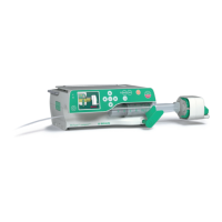
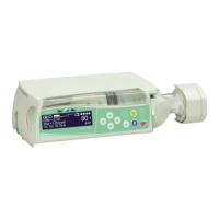
Perfusor® compact, 3.1 gb 4- 11
tables differ provide the unit with the new table supplied with the
E-Module.
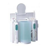
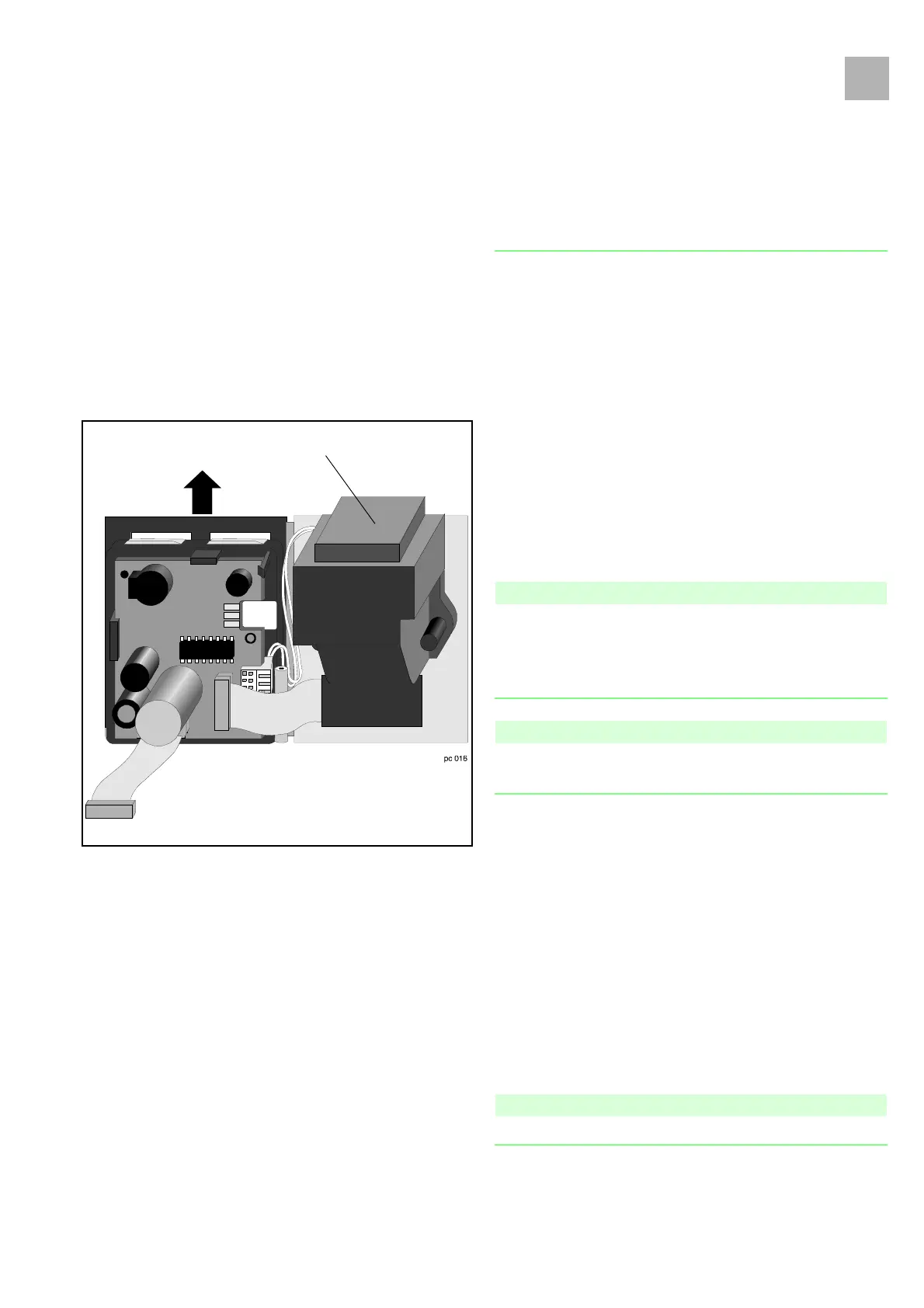
4.10 N-Module
Designation Ord. No.
N-Module (220 -240 V) . . . . . . . . . . . . . . . . . . . . . . . . 3450 6683
N-Module (100 -120 V) . . . . . . . . . . . . . . . . . . . . . . . . 3450 6730
Exchange
1. Open housing (see "Open unit" ➨ p. 4 - 3).
2. Remove MFC socket.
3. Pull off the N-Module connector on the A-Module (slightly
pull out the A-Module).
4. Loosen both screws (on the rear) and exchange N-Module.
5. Assembly is performed in reverse order.
Note
Lay two-wire cable with mains power connector behind bearing.
Connect mains power connector correctly to the A-Module
(please see figure). Do not squeeze the cable (see "Close Unit"
➨ p. 4 - 4).
Note
The connector on the E-Module can be easily connected when the
E-Module is swiveled out (see "E-Module" ➨ p. 4 - 10).
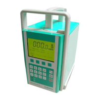
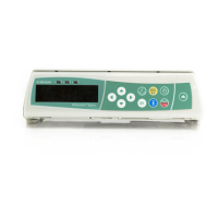
4.11 Housing Upper Part, Complete
Designation Ord. No.
Housing upper part incl. membrane keyboard, . . . . . . 3450 6586
carrying handle and LS-clip
Exchange
1. Open housing (see "Open unit" ➨ p. 4 - 3).
2. Modify modules.
3. Close housing.
Note
Do not squeeze the cable (see "Close Unit" ➨ p. 4 - 4).
Fig.: 4 - 12
N-Module
3.1