Classic Cycles Technical Resources
35
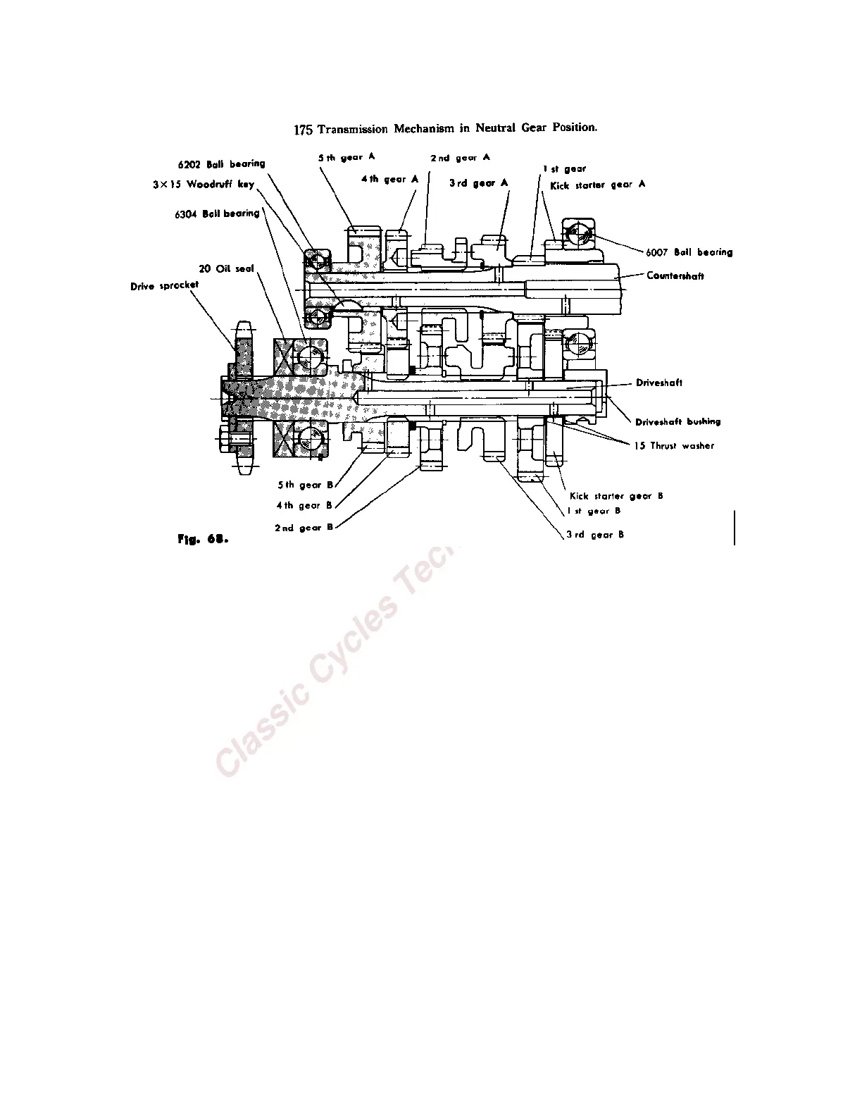
The gears are so installed that the drive dogs on one gear engage the holes in the gear next to it. Gears are
never installed with drive dogs facing each other. Also, the respective gears will fit only one shaft properly.
Hence, all gears will mesh and drive dogs will properly engage the neighboring gears.
B. Gear Shift Mechanism
The Gear Shift Mechanism consists of a shift drum-shift fork assembly, shift drum pawl and shift arm
assembly, drum stopper, gearshift shaft and shift pedal.
1. Shift drum-shift fork assembly.
The shift drum is cylindrical in shape and it has a spiral-like groove (two in 175DT) cut into its surface into
which the shift forks are fitted. The rotary motion of the shift drum is translated into side-to-side motion in
the shift forks as they move in the spiral groove. The shift forks, in turn, move the sliding transmission
gears from side to side, thus shifting the various gears in the drive train.
2. Shift Drum Pawl.
The shift drum pawl is attached to the shift arm and serves to rotate the shift drum by means of pulling or
pushing action on the shift pins attached to the end of the shift drum.
3. Drum Stopper.
The shift drum stopper holds the shift drum in position between gear shift operations by lodging between
the drum shift pins.
4. Gearshift shaft.
The gear shift shaft serves to connect the shift arm and shift pawl to the footoperated gearshift lever.
5. Gearshift Lever.