Classic Cycles Technical Resources
57
2. For chronic problems caused from the cycle being driven only at very low speeds, the charging coil from
the B/S 7 Standard can be installed to increase charging.
NOTE: When either method is used, battery water should be checked frequently and water added as
necessary.
ELECTRICAL EQUIPMENT – 175 DT
The ignition system consists of contact breakers, condensers, ignition coil, spark plugs, etc. Battery low
voltage current is converted to high voltage current by the ignition coil. High voltage current is supplied to
the spark plug and, when timed by the contact breakers, ignites the fuel mixture in the cylinder.
Contact Breakers: Two contact breakers are fitted on the AC dynamo. The AC dynamo is turned through
the pinion drive gear, driven gear and timing gear. The timing gear turns one full revolution when the
crankshaft turns two full revolutions. The timing gear and point cam are fixed on the dynamo shaft and
turn with it. The engine of the BS 175 DT is a two-stroke two cylinder engine so two explosions occur every
time the crankshaft makes one full revolution. As the speed of the AC dynamo is one-half of that of the
crankshaft, contact points must supply four sparks for each revolution of the dynamo, so two cams and two
sets of contact breakers are installed. One contact breaker opens each 90E (¼ turn) of cam rotation and high
voltage current is induced in the ignition coil.
Contact breaker points should be kept bright and
smooth. If point surfaces are rough or pitted, polish
lightly and evenly on an oil stone until the surfaces are
smooth. (If points cannot be repaired, replace with new
ones.) After polishing, wash the point surfaces with
gasoline or thinner and wipe dry with a clean cloth.
Ignition timing:
• NOTE: Do not attempt to adjust left timing until
right timing is completed. Movement of generator
during right cylinder timing adjustment will change
left timing.
TO CHECK TIMING - RIGHT CYLINDER
1. Remove spark plugs.
2. Remove left carburetor air pipe.
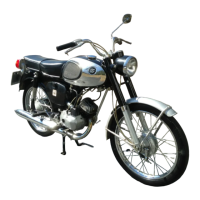
3. Remove point cover from left end of generator and adjust both
sets of points to .012"-.016" at their widest point.
4. Rotate crankshaft by putting transmission in 4th gear and
turning rear wheel until the right piston is at top dead center as
viewed through the spark plug hole.
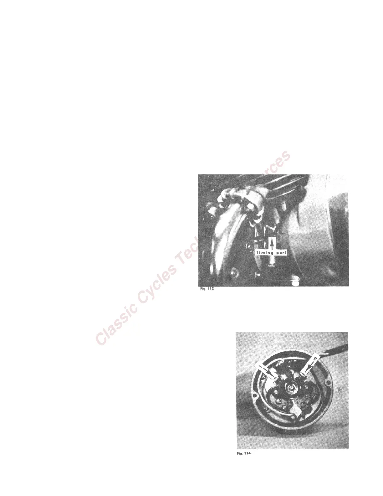
5. Install timing screw and bar into timing hole at front of engine
(fig. 112). This item is packed in the cycle tool kit.
6. Connect one lead wire of a continuity test light to the right point
condenser lead wire at the condenser with the key switch in the
off position. (Test light is now off) The other test light lead wire
is grounded to engine.