Classic Cycles Technical Resources
19
33. Lift the fifth speed shift fork to the right so
that the guide pin spring and spring seat can
be removed from the shift fork.
34. Holding the neutral switch in place on the end
of the shaft, remove the transmission selector
shaft from the crankcase.
35. Remove the oil splash shield from the
transmission case.
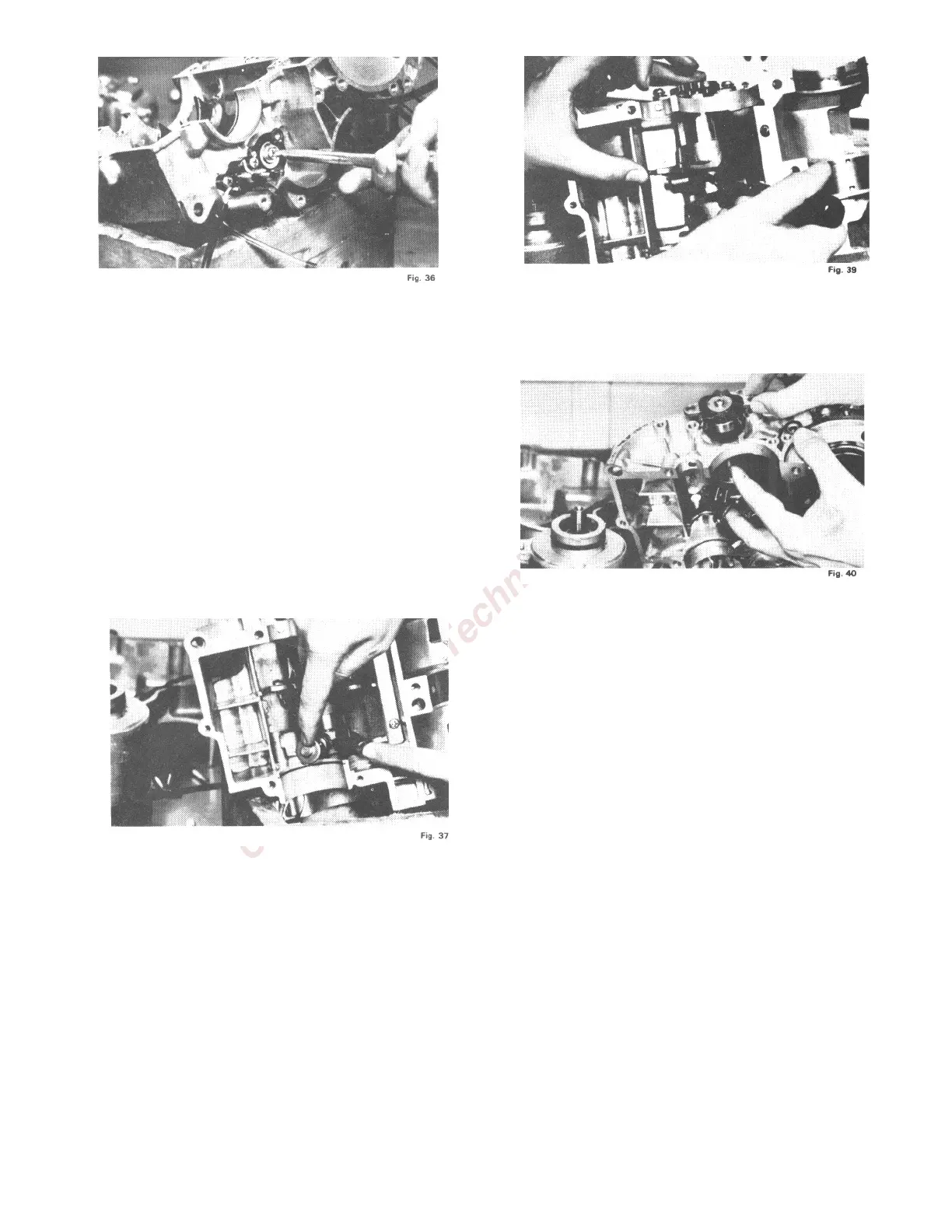
36. Remove the cotter pins from the shift forks.
37. Using a screw driver, tip the shift fork guide
pins out of the groove in the shift drum.
38. Remove the thrust receiver mounting screws
and pull the shift drum and thrust receiver
out of the transmission case. Hold the shift
forks stationary while the shift drum is being
removed. Remove the shift forks from the
transmission case.
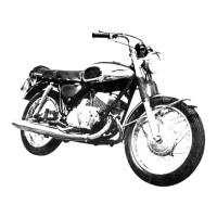
39. Remove the guide pins from the shift forks
and inspect them for wear. Notice that the
guide pins are equipped with roller ends.
These roller ends ride in the grooves in the
shift drum.
40. Remove the spring clip which retains the kick
starter shaft in the lower crankcase section.
41. The kick starter shaft can then be withdrawn
from the crankcase section. Remove the
ratchet assembly from the crankcase section.
Before reassembling the engine, wash all parts in
a cleaning solvent; inspect for abnormal wear.
III. ENGINE REASSEMBLY
1. If the neutral switch was removed from the
transmission selector lever shaft, re-install the
switch assembly onto the transmission selector
lever shaft. Be certain that the contact is not
out of round and that it is properly seated in
the groove provided for it on the plastic
portion of the shaft.
2. Install the shaft, onto which the switch
assembly has been mounted, into the
transmission case. Secure it with two Phillips
head screws.
3. Connect one lead of a continuity tester to one of
the leads from the switch cover and ground
the other continuity tester lead. Rotate the
selector lever shaft until the continuity tester
lights. Connect the lead of the continuity to
the other switch case lead and with the other