16
17. Remove the control cable from the oil injection
pump control arm by prying the cable
attaching bracket open with a screw driver.
18. Remove the throttle cable adjusting screw out
from the transmission cover.
19. Remove the main oil pump supply line from
the fitting on the oil pump and plug this oil
line with a screw to prevent the oil from
draining out of the supply tank.
20. Remove the saddle.
21. Remove the side cover from the left hand side
of the cycle.
22. Disconnect the wiring running between the
AC generator and the battery. These wires are
snap connected.
23. Disconnect the wires from the terminals on
the selenium rectifier. The wiring harness can
then be pulled free of the cycle.
24. Disconnect the master link on the drive chain
and remove the chain from both sprockets.
25. Disconnect the exhaust pipe clamps and
swing the exhaust pipes down, clear of the
engine.
26. Remove the air cleaner.
27. Remove the four engine mounting bolts from
the mounting plates at the front of frame
assembly.
28. Remove the lower rear engine mounting bolt.
29. Remove the upper rear engine mounting bolt.
This bolt should be withdrawn with a pliers
since all of the engine weight is now bearing
against this last bolt.
30. Remove the engine from the cycle frame.
II. ENGINE DISASSEMBLY
1. With the engine placed on a suitable bench,
remove the cylinder heads and cylinders.
2. Remove the piston pin retaining clips and,
using the piston pin pusher from the
Bridgestone Special Tool Kit, remove the
piston pins and pistons.
3. Remove the connecting rod needle roller
bearings.
4. Remove the oil lines from the oil pump.
CAUTION: If the union bolts are removed
from the banjo connectors use care to avoid
losing the ball check valves from the union
bolts. NOTE: The earliest BS175 models were
not equipped with ball check valves in the
union bolts.
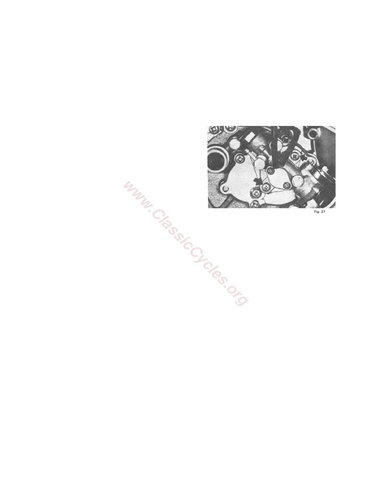
5. Remove the two screws which mount the oil
pump to the oil pump gear box.
6. Remove the four oil pump gear box mounting
screws. It will be necessary to rotate the pump
to remove the last two screws.
7. Remove the oil pump and gear box assembly
from the rotary valve cover.
8. Remove the left hand crank case cover.
9. Remove the rotary valve cover. CAUTION: If
it is necessary to pry this cover to remove it
from the crankcase, use extreme caution. Pry
only in the area immediately adjacent to
rotary valve cover locating pin. Prying may
cause damage to the crankcase which will
result in leaks.