50
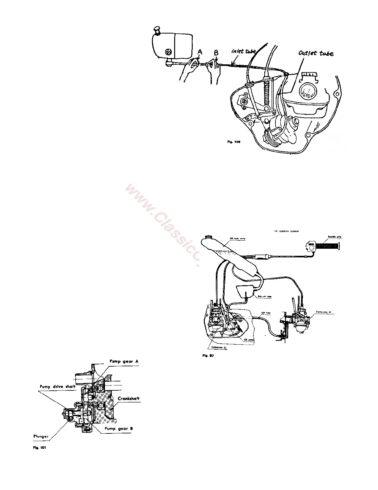
• NOTE: Pinch part A first, then
pinch part B; repeat alternately
until air bubbles are eliminated and
the oil flows freely out of the union
bolt.
5. Tighten the oil inlet union bolt and
repeat pinching with fingers; check
the oil flow in the outlet tube
(transparent) to the inlet in the
rotary valve cover.
• If there is no oil flow in the outlet
tube (transparent), repeat
procedure 4.
A simple check of the oil injection
system can prevent serious damage
when the machine is operated. Dirty or plugged oil lines, tanks, or filter could prevent the oil flow from the
oil tank to the pump.
Whenever a new cycle is serviced, the oil supply line to the pump should be removed at the pump and
checked for oil flow.
If a good supply of oil is not available at this line, check the tank, filter and lines and correct as necessary.
Oil must flow freely from this line to supply the engine with the proper lubrication.
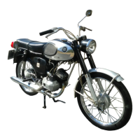
OIL INJECTION SYSTEM – 175DT
A. Construction and Operation:
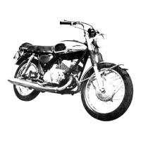
Lubricating oil is supplied by an oil pump attached to
the left rotary valve cover. Oil pump gear B, attached to
the pump drive shaft, is driven by gear A, located on the
left end of the crankshaft.
The oil pump Drive Shaft drives the pump plunger
through a worm gear arrangement. The speed at which
the Plunger rotates, then, is determined by crankshaft
RPM. There is a 12:1 reduction in the gearing between
the crankshaft and the pump drive shaft.
In addition to being rotated by the pump drive shaft, the
Plunger moves up and down in the pump body. This
reciprocating
motion is produced by the cam-shaped lower end of the Plunger
bearing against the Plunger Guide.
The Plunger is held against the Plunger guide by the spring-loaded
Differential Plunger which bears against the top of the Plunger.
The length of the Plunger stroke is determined by the position of
the Stop cam in the lower end of the Pump Body. The stop cam is
part of the control arm assembly which is connected by means of a
control cable to the throttle grip.