24
54. Replace the oil level screw and fiber washer
and install the right hand oil pump attaching
screw. Tighten securely.
55. Using the pressure type oil can, fill the right
hand oil injection line before installing a line
onto the right banjo connector. When
tightening the banjo connector union bolts use
caution, so as not to overtighten the bolts.
These bolts are hollow and can be broken.
Note that a washer is used on either side of all
banjo connectors.
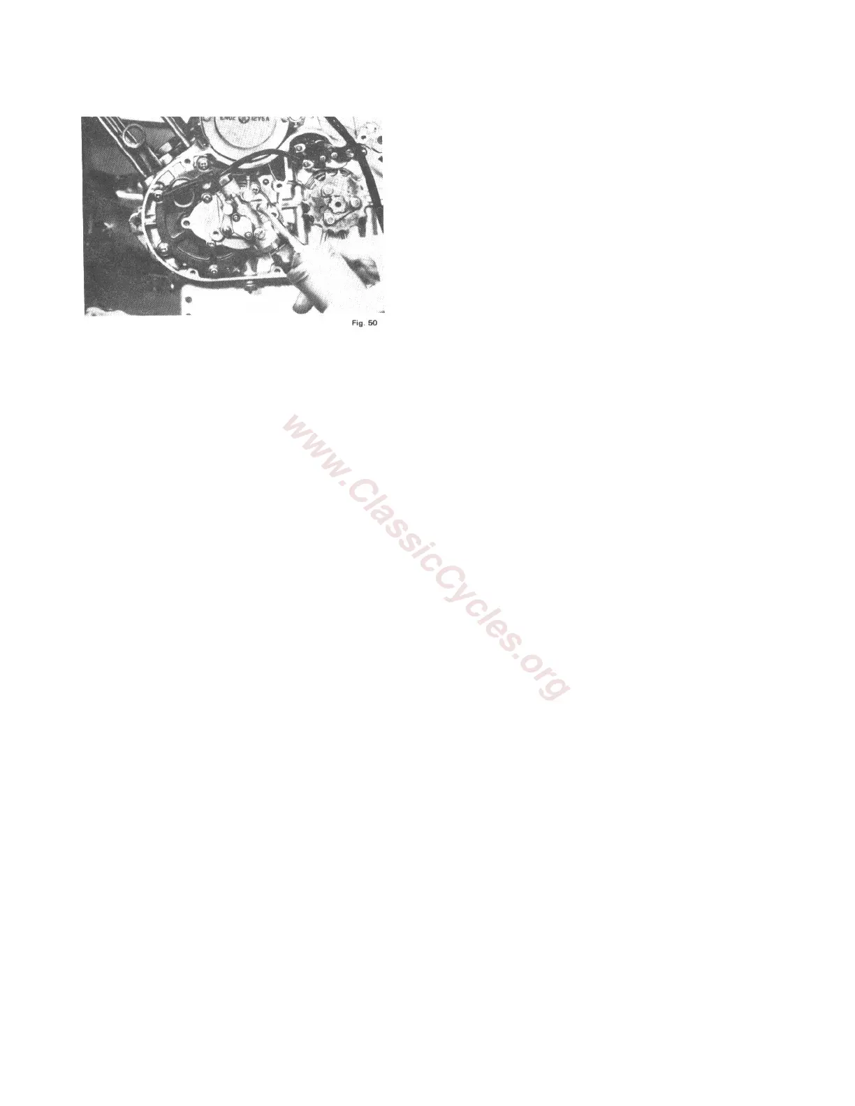
56. Install the left oil line onto the oil pump and
onto the left rotary valve cover.
57. Install the left crackcase cover. It may be
necessary to adjust the position of the oil lines
when this cover is installed to be certain that
there are no sharp bends in the oil lines.
58. Install the cylinder base gaskets onto the two
sets of cylinders studs.
59. Install the piston pin needle bearings into the
upper ends of the connecting rods and oil them
generously.
60. Install the pistons.
61. Install the piston pins retaining clips. Make
certain that they art securely seated in the
grooves provided for them in the pistons.
62. Coat the cylinder walls with oil and install the
cylinders onto the cylinder studs.
63. Install the cylinder head gaskets and cylinder
heads. When installing the cylinders heads,
position the heads so that the small key stone
trademark on the underside of the cylinder
head faces the front of the cylinder. Torque the
cylinder nuts to 140 inch pounds.
IV. INSTALLING ENGINE INTO FRAME
1. Position the engine in the frame and install the
two rear mounting bolts. Install the front
mounting bolts and attaching plates and
tighten securely.
2. Install the new gaskets and connect the
exhaust pipes to the cylinders.
3. Install the clutch cable and cable adjusting
screw into the crankcase assembly.
4. Install the clutch release arm onto the release
screw after connecting it to the clutch cable.
Connect the return spring to the spring pin.
5. Adjust the clutch cable until a center-to- center
distance of 1¼ inches is obtained between the
clutch release arm pivot pin and spring
attaching pin. Tighten the cable adjusting
screw lock nut securely.
6. Turn the clutch adjusting screw until
approximately 3/8 of an inch of lever free play
is obtained. The free play is measured at the
lever end. Tighten the adjusting screw lock
nut.
7. Install the left carburetor.
8. Attach the control cable to the oil pump control
arm. Bend the tab on the arm to secure the
cable.
9. Adjust the control cable by turning the cable
adjusting screw so that, at the full throttle
position, there is approximately 1/8 inch of
clearance between the control lever and the
stop pin. When this clearance is obtained,
tighten the cable adjusting screw lock nut.
10. Attach the main oil supply line to the center
banjo connector on the oil pump. You will
recall that we previously plugged this line
with a screw to prevent oil from running out of
the supply tank.
11. Install the left carburetor cover using a new
gasket.
12. Reinstall the drive chain and install the
connecting link spring clip so that the open
end of the clip faces the direction opposite of
the direction chains rotation.