Classic Cycles Technical Resources
23
38. Install the generator strap and mount the
generator. Do not tighten the generator
mounting bolts securely.
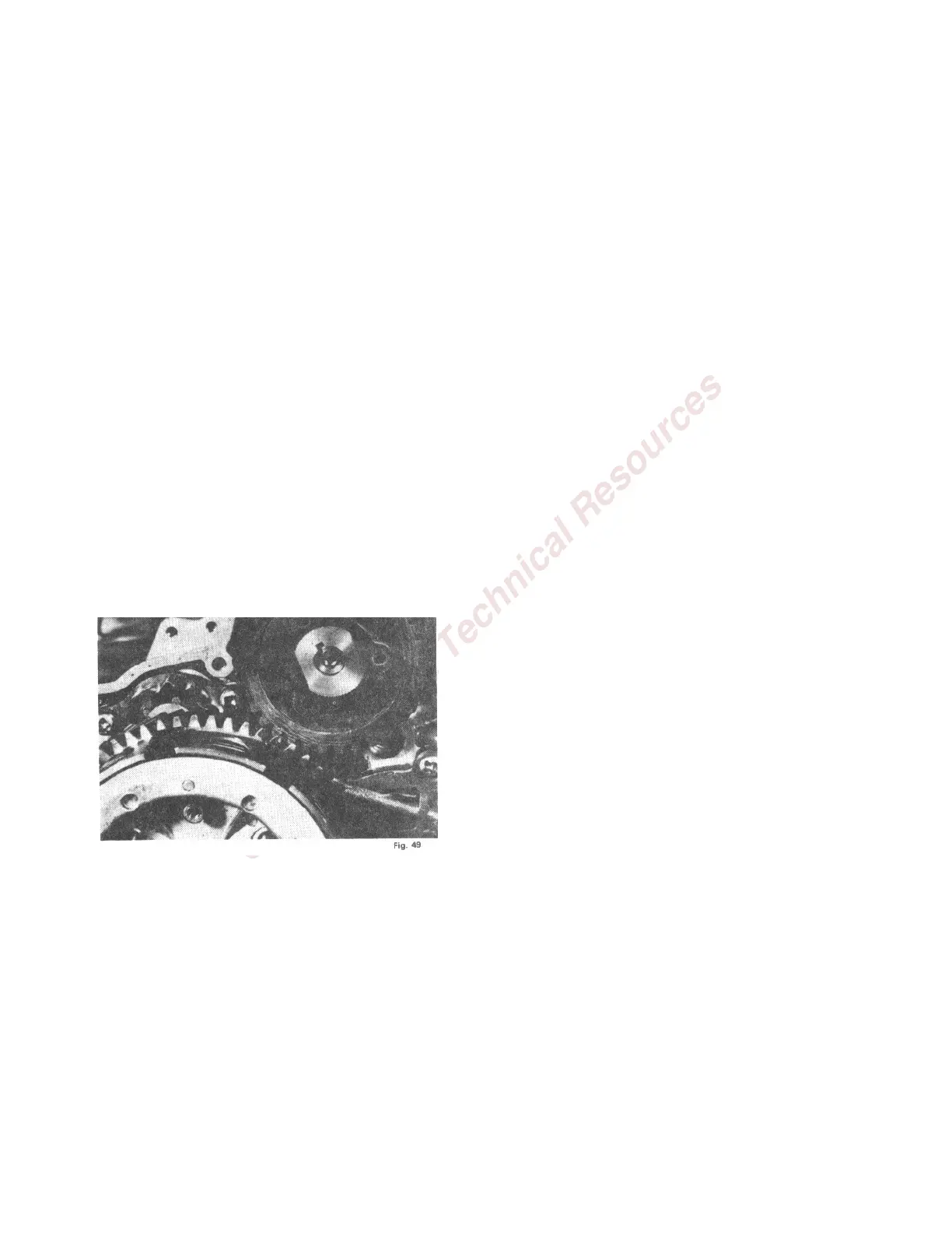
39. Again, facing the right hand side install the
generator gear so that the marked tooth on
this red fiber gear is aligned with this upper
most of the two marks on the clutch gear. Be
certain that the generator gear is on the
woodruff key in the generator shaft. NOTE:
THE POSITION OF THE PINION GEAR,
CLUTCH GEAR, AND GENERATOR GEAR
AS REFERENCED BY THE MARKED
TEETH IS ESSENTIAL. IF THESE GEARS
ARE NOT PROPERLY ALIGNED AND THE
PINION GEAR IS NOT PROPERLY
POSITIONED ON THE MARKED SPLINE
OF THE CRANKSHAFT, IGNITION TIMING
WILL BE IMPOSSIBLE.
• NOTE: The timing idle gear on those models
after serial No. l6G 11761 is installed just
prior to the generator gear. WITH THE
PINION GEAR ALIGNED WITH THE
CLUTCH GEAR, THE GENERATOR GEAR
IS INSTALLED SO THAT THE PUNCH
MARK ON THE GENERATOR GEAR
ALIGNS WITH THE CENTER OF THE
FIBER IDLE GEAR.
40. Install the kick starter shaft return spring.
Hook the lower end of the spring into the
crankcase and hook the upper end of the
spring into the countersunk hole in the starter
shaft. The starter shaft is to be rotated
clockwise and held in position while the spring
is wound counter-clockwise to install it into
the hole in the shaft.
41. Install the spring cap to prevent the spring
from becoming unhooked.
42. Install the knock pins into the crankcase
assembly and place a new gasket over the
knock pins.
43. Install a new "O" ring on the carburetor
adapter.
44. Coat the clutch release screw roller bearing
with heavy grease to hold it in place in the
release screw. Install the transmission cover
and tighten the screw securely.
45. Turn the engine around so that you face its
left side.
46. Coat the left rotary valve cavity with oil and
install the left rotary valve aligning the letter
"L" stamped on the valve with the pin in the
crankshaft.
47. Inspect the left rotary valve cover to be
certain that the large "O" ring is in place and
that the center oil seal is in good condition.
48. Install the left rotary valve cover, locating it
on the crankcase by means of the pin in the
crankcase and the hole in the cover. Secure
the cover with four short screws. The two
remaining screws are not installed at this time
because they also secure the oil pump gear
case.
49. Using a new gasket install the oil pump and
oil pump gear case assembly onto the left
rotary valve cover, locating the gear box by
means of the two pins in the rotary valve
cover.
50. Install the four screws which secure the gear
box to the rotary valve cover.
51. Install the screw on the left side of the oil
pump which secures the oil pump to the gear
box.
52. Remove the oil pump gear box oil level screw.
This screw can be identified by the red fiber
washer beneath it.
53. Using a pressure type oil can inject oil
through the screw hole on the right side of the
oil injection pump until oil is seen coming out
of the oil level screw hole. NOTE: The oil
pump gear cavity on those models after serial
No. l6G 11761 is lubricated automatically from
the transmission.