Classic Cycles Technical Resources
47
OIL INJECTION SYSTEM – 90cc
In the conventional two-stroke engine, a fuel mixture of
gasoline and lubricating oil is used so that parts inside the
engine are lubricated by oil contained in the fuel mixture. In
the Bridgestone Oil Injection System, a premixed fuel is not
necessary; gasoline and oil are supplied separately to the
engine. Gasoline is supplied through a carburetor as in the
conventional system.
A. Construction and Operation:
The oil injection pump is installed in the transmission case.
The pump works as follows:
The worm wheel of the pump is driven through:
Crank shaft – Drive pinion – Pump Gear B
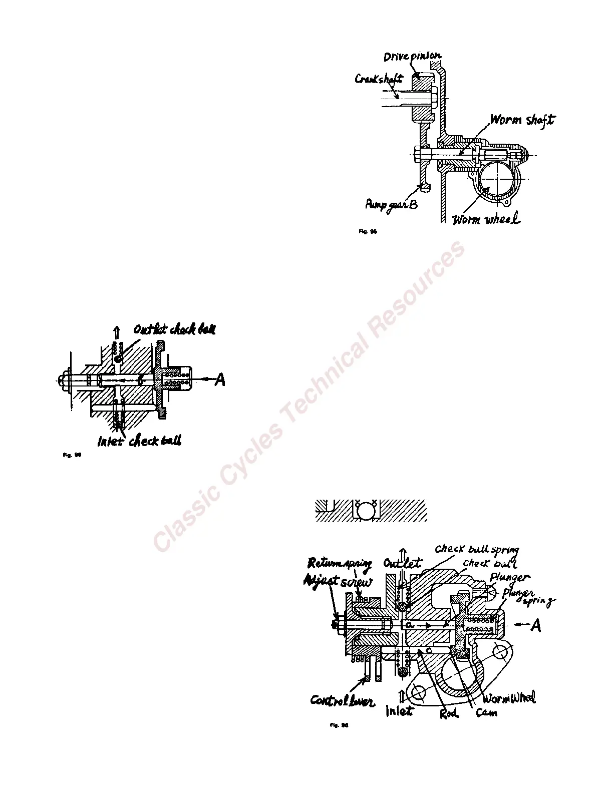
The worm wheel, the boss of which is cam-shaped, is in addition to being rotated by the pump drive shaft,
pushed in direction B by the plunger spring and contacts the rod (c) as shown in Fig. 96. The worm wheel
plunger slides in the direction of (a) or (b) shown by arrows in Fig. 96 and 98, following the cam height.
1. Oil Intake:
When the worm wheel contacts the rod (c) at the highest point of the
cam, the volume of the pump chamber increases and the pressure in
the chamber (Fig. 99) decreases and releases the inlet check ball. The
inlet port opens and oil is sucked into the oil pump chamber.
2. Oil Outlet:
When the worm wheel plunger slides in the direction (b) illustrated
by the arrow in Fig. 98 the volume of the pump chamber decreases.
By decreasing the volume of pump chamber, the inlet check ball
closes the inlet port and the outlet check ball opens the outlet port.
Oil is forced into the crankcase.
3. Operation of Worm Wheel Plunger in Relation to
Throttle Grip:
(a) Slow speed—idling:
When the throttle grip is in zero position, i.e.
throttle grip is in closed position, the rod (c)
contacts the control lever at its lowest position. The
worm wheel plunger slides to the left (arrow "a")
and the plunger contacts the adjusting screw as
shown in Fig. 98. The distance of shift of the
plunger to the adjusting screw (d) is shortened to
less than the height of the worm wheel cam,
thereby reducing the volume of oil.
(b) High speed — wide open throttle: