48
When the throttle grip is wide open, the cam of the control lever contacts the rod (c) at its highest point,
thereby shifting the rod (c) to the right (arrow A).
The distance of shift of the plunger is lengthened, and the volume of oil increased.
B. Adjustment:
The oil pumps used on B/S 90 machines are factory adjusted for the proper amount of oil and should never
need adjusting. The only time adjusting should be necessary is when a customer or an unauthorized
personnel may have tampered with the adjustment.
If the setting needs adjusting, proceed as follows:
Note: Use extreme care when making this adjustment and follow these instructions exactly.
TO REMOVE AND DISASSEMBLE THE PUMP
• Remove the 2 pump mounting screws.
• Disconnect the pump control cable from the control arm.
• Disconnect the inlet and outlet oil lines from the pump. Caution: Care must be used not to lose the balls
and springs from the connecting bolts.
• Remove the pump from the engine.
• Disassemble the pump by removing 3 pump housing screws and separate the two pump halves.
Caution: Locate the spring in the end of the pump gear so that it does not become lost.
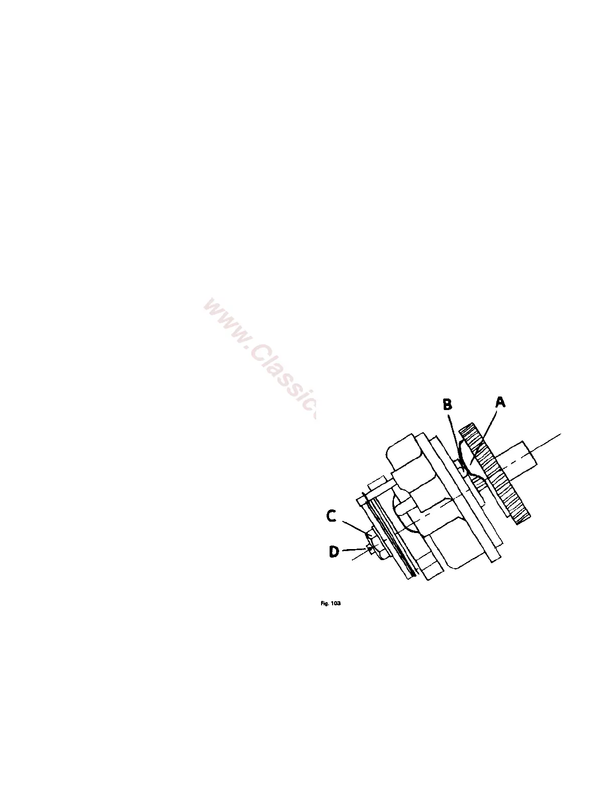
TO ADJUST THE PUMP
1. Hold the pump in the position shown below and
revolve the pump gear so that the highest point of
its earned edge "A" is in contact with the stop pin
"B".
2. Loosen the adjusting screw lock nut "C'
3. Turn the adjusting screw "D" in (clockwise) until it
pushes the pump gear out just to the point where
the stop pin "B" is just contacting the high point of
the cam "A". Check by revolving the pump gear
while holding it in against the adjusting screw, to
see that the gear does not move in and out when it
moves from the high to the low point of the cam.
The stop pin "B" should just touch the high point of
the cam when it is revolved.
4. When the screw "D" has been set so that the stop
pin "B" is just touching the high point of the cam, turn the adjusting screw "D" out (counterclockwise)
exactly ¾ of a turn and secure with the locknut "C".
The pump is now correctly adjusted for all driving speeds.
TO REASSEMBLE THE PUMP
1. Install the gear spring into the pump gear.