22
Left and right sides of the engine are
determined by facing the direction in which
the machine travels.
33. The edges of the washer are bent up against
the flats of the nut to prevent its loosening
during operation.
34. Install the six clutch springs and install the
clutch thrust plate. Be certain that the ball
bearing on the thrust plate faces out.
35. Install the pinion gear onto the crankshaft.
• ALIGN THE MARKED TOOTH ON THE
GEAR WITH THE PUNCH MARK ON ONE
OF THE CRANKSHAFT SPLINES.
27. Install the small "O" ring which seals the oil
passage for the oil injector to the right
carburetor adapter.
28. Install the crankshaft collar.
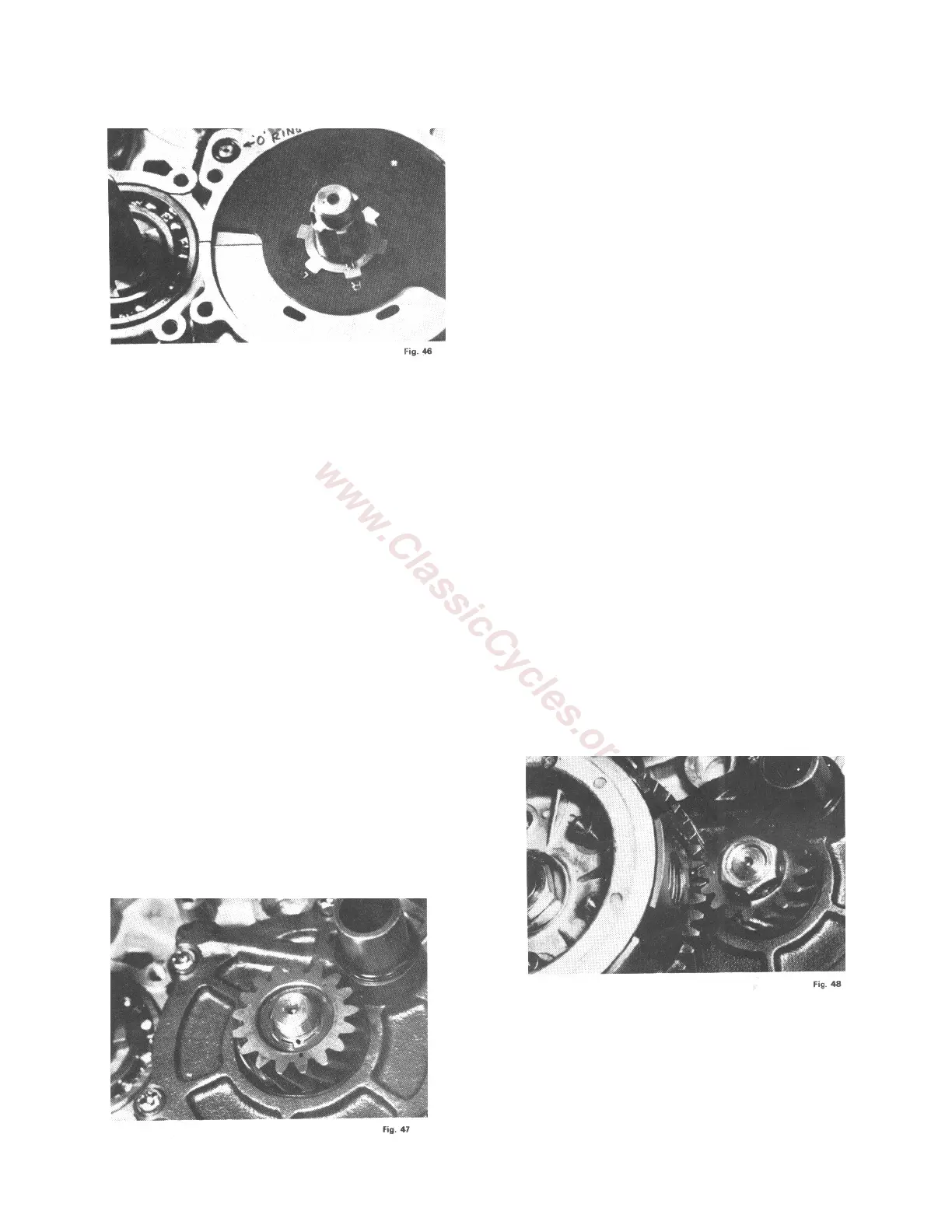
29. Install the right rotary valve cover. Before
installing check to be certain that the 100mm
"O" ring is in good condition and in place in
the groove provided for it in the rotary valve
cover. Also check the condition of the center oil
seal. The rotary valve cover is installed by
aligning the pin
30. Locate the two punch marks on the clutch
gear. These marks are located between gear
teeth approximately three inches apart.
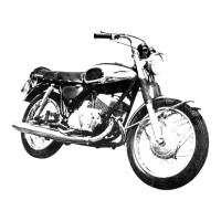
31. Install the clutch onto the transmission
countershaft. NOTE: On newer models, fit the
thrust spring over the clutch drive gear,
install the clutch assembly, except for the hub,
replace the splined washer, and then install
the clutch hub.
32. Secure the clutch with the bend washer and
hex nut. The clutch stopper is installed to
prevent the clutch from rotating during
tightening of this nut.
33. The edges of the washer are bent up against
the flats of the nut to prevent its loosening
during operation.
34. Install the six clutch springs and install the
clutch thrust plate. Be certain that the ball
bearing on the thrust plate faces out.
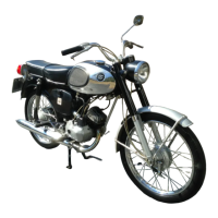
35. Install the pinion gear onto the crankshaft.
• ALIGN THE MARKED TOOTH ON THE
GEAR WITH THE PUNCH MARK ON ONE
OF THE CRANKSHAFT SPLINES.
• THIS MARKED TOOTH MUST ALSO BE
ALIGNED WITH THE LOWER OF TWO
PUNCH MARKS ON THE CLUTCH.
• Install the spring washer and hex nut. This is
a left hand thread.
36. Put the piston seat in place under the
connecting rod upper end and tighten the
pinion gear nut securely.
37. Turn the engine around so that you face its
left side.