Classic Cycles Technical Resources
21
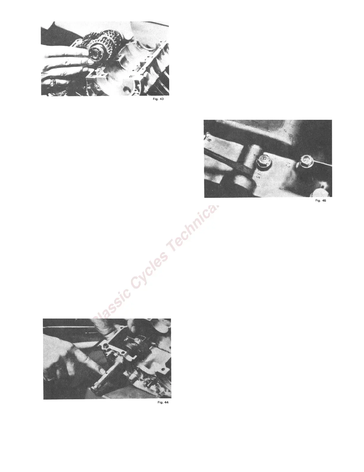
15. Install the clutch shaft. Note that the
smaller ball bearing on this shaft has the one
sealed side. The sealed side of the bearing is to
face the gears. The open side faces out. Note
that the clutch shaft is hollow. Oil is deflected
by the splash shield into the cavity next to the
sealed bearing. It then passes through the
shaft, lubricating the gears on the shaft.
Check the shafts for freedom of rotation.
16. Place the thrust washer in the kick starter
ratchet gear and install the ratchet arm and
pawl assembly on top of the thrust washer.
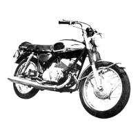
17. Holding the kick starter gear and ratchet
stopper assembly in position in the crankcase
section, install the kick starter shaft into the
crankcase. Locate the splined portion of the
shaft into the kick starter ratchet arm so that
the countersunk hole in the shaft faces up
when the ratchet arm is resting against the
ratchet stopper. This positioning of the shaft is
necessary to secure the proper tension on the
kick starter return spring when it is installed.
Be certain that the small thrust washer is in
place on the end of the shaft is inserted into
the boss provided for it in the crankcase.
18. Insert the spring clip onto the shaft behind
the ratchet stopper.
19. Coat the abutting surfaces of the two
crankcase sections with a rubber-base gasket
compound such as Pliobond.
20. Install the 2 knock pins into the upper
crankcase section and join the two sections.
Place all of the joining bolts into the holes
provided for them and check to see that
approximately ½ inch of thread is available
between the bolt head and the crankcase
before tightening any of the bolts.
21. Tighten all bolts finger tight.
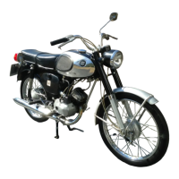
22. Then tighten the bolts in the tightening order
which is embossed on the crankcase next to
the bolt holes. The bolts with the large heads
are torqued to 120 inch pounds and the
smaller bolts are torqued to 60 inch pounds.
23. Install the bearing retainer on the right hand
side of the engine assembly with the three
screws provided.
24. Check to be certain that the spacer washer is
on the gear shift shaft assembly and install the
shaft onto the transmission case. Place the
shifter pawl into the shift drum. Check it for
freedom of movement.
25. Install the shift drum stopper. Note that a
spacer washer is used behind the stopper and
the shoulder bolt passes through the drum
stopper and spacer and threads into the boss
in the crankcase. Connect the drum stopper
spring and check the drum stopper for freedom
of movement.
26. Install the right rotary valve. Note that the
rotary valves are interchangeable and are
marked with the letters "L" and "R". The.
rotary valve on the right hand side of the
engine is installed so that the letter "R" is
aligned with the pin in the crankshaft. Note: