20
continuity tester lead grounded, again rotate
the shaft until the continuity tester bulb
lights. If the bulb will not light in both
positions, check the installation of the switch
contact and, if it is out of round, replace it.
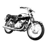
4. Place the fifth speed shift fork into the
transmission case so that the guide pin boss
faces the transmission selector lever shaft.
NOTE: For installation of the modified shift
fork, which appears on models after serial No.
16B 04739, see page 38, under
TRANSMISSION.
3. Fit the two main shift forks (which are
identical and interchangeable) together and
place them in the transmission case.
6. Place the thrust receiver in position in the end
of the shift drum and insert the shift drum
through the transmission case and through all
three shift forks. Secure the thrust receiver
with the two mounting screws and star
washers.
7. The guide pins are inserted into the main shift
forks so that the roller ends are positioned in
the shift drum groove. Install the cotter pins
in the shift forks so that the cotter pins may be
spread around the curved part of the guide pin
bosses.
8. Install the fifth speed guide pin spring and
guide, tipping the shift fork to your left so that
the guide pin is retained in the notch in the
selector lever shaft.
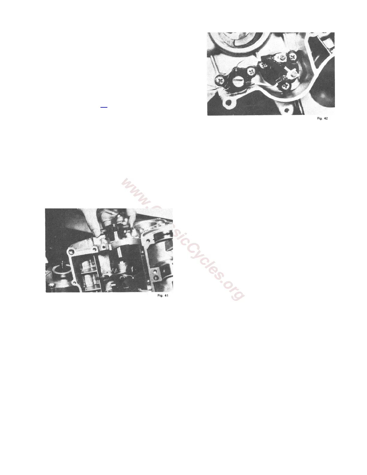
9. Install the neutral switch contact onto the end
of the shift drum.
10. Install the neutral switch cover over the shift
drum contact. This cover must be installed so
that the wires from the terminals on the
selector shaft switch marked "4" and '"5" are
connected to the shift drum switch cover
terminals marked "4" and "5", respectively,
without crossing the wires.
11. Placing the selector lever shaft and sprocket
cover in position, turn the selector lever shaft
to the four speed position. Connect one lead of
the continuity tester to the yellow wire with
green tracer running from the main neutral
switch. Ground the other lead. Rotate the shift
drum until the gears are in the neutral
position and the continuity tester light goes
on. Place the transmission in any gear. Using
the selector lever, move the shaft to the five
speed position. Rotate the shift drum until the
continuity tester light comes on. If you do not
get a light in both the four speed and five
speed neutral positions, inspect the contact on
the shift drum. Replace if necessary.
12. Install the crankshaft assembly.
13. Install the oil splash shield.
14. Install the transmission drive shaft locating
the groove on the large ball bearing onto the
bearing locating ring in the crankcase section.
The bushing on the other end of the shaft is
located on a knock pin in the crankcase
section.