FT800 Series Programmer Guide
Version 2.1
Document Reference No.: BRT_000030 Clearance No.: BRT#037
20
Product Page
Document Feedback Copyright © Bridgetek Limited
After the above drawing commands are loaded into display list RAM, register
REG_DLSWAP is required to be set to 0x02 in order to make the new display list active
on the next frame refresh.
Note:
The display list always starts at address RAM_DL
The address always increments by 4(bytes) as each command is 32 bit width.
Command CLEAR is recommended to be used before any other drawing
operation, in order to put FT800 graphics engine in a known state.
The end of the display list is always flagged with the command DISPLAY
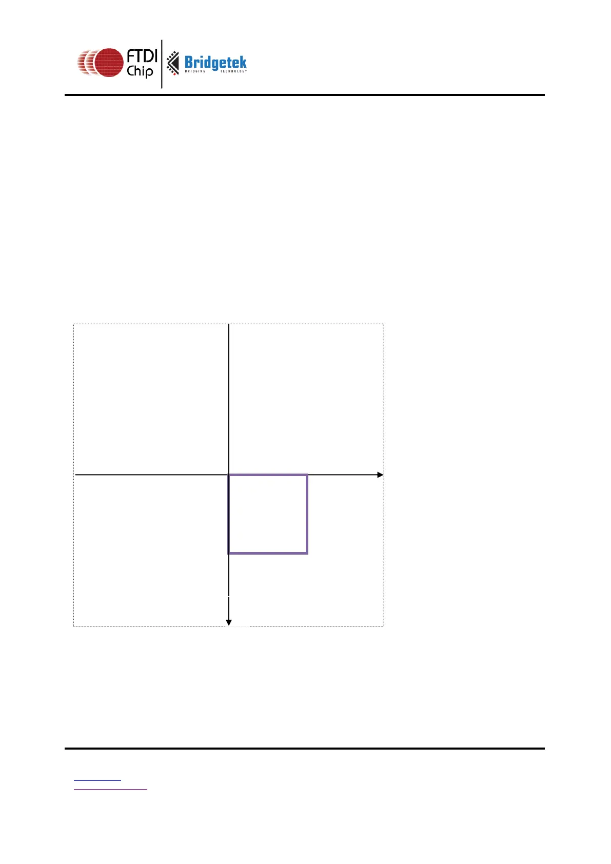
2.5.2 Coordinate Plane
The figure below illustrates the graphics coordinate plane and its visible area.
The valid X and Y coordinate ranges from -1024 to 1023 in pixel precision, i.e., from
-16384 to 16383 in 1/16
th
pixel precision.
Figure 7: FT800 graphics coordinates plane in pixel precision