Polycold Cryochiller Installation
Installation and Operation Manual Insulate Exposed Refrigerant Tubes and Couplings
Brooks Automation
214072 Revision B 4-41
3. Open the cold box on the right top panel of the refrigeration unit and locate the red hand valves.
4. Locate the valves labeled as follows: See Figure 4-31.
• MV101 - Hot Gas Feed
• MV102 - Cold Gas Feed
• MV103 - Common Return
5. Turn each of these hand valves completely counter-clockwise to fully open each valve.
6. Turn each hand valve clockwise 1/4 turn from full open.
7. Wait 10 minutes for the pressure to equalize in the system.
The pressure may drop 35-70 kPa (5-10 psig) as the refrigerant mixture enters the refrigerant line
and cryosurface.
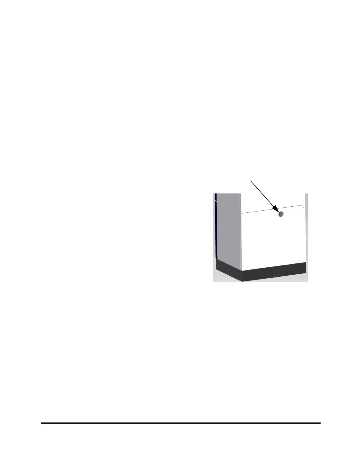
8. If the back side of the system is not accessible, dis-
regard this step.
If the back side of the system is accessible, locate
the pressure gauge and read the pressure value.
This is the Static Pressure. See Figure 4-32
Record the pressure reading in a maintenance log
for future reference.
9. Inspect the valve box cover to make sure the rub-
ber seals are intact.
10. Reinstall the valve box cover and securely screw it
into place, covering the hand valves. The gasket
should form a seal to keep out water vapor.
11. Start the cooling water.
12. Confirm the cooling water flow meets specifications
found in Cooling Water on page 3-6.
13. Go to the Installation Checklist Table 4-1. Initial and date this task. Go to the next task on the check-
list.
Insulate Exposed Refrigerant Tubes and Couplings
Properly insulating the exposed tubes and couplings keeps them dry. Penetrating moisture adds heat
load to the cryopump and can cause corrosion or leaks.
Figure 4-32: Pressure Gauge on
Back of Refrigeration Unit
Pressure Gauge