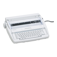
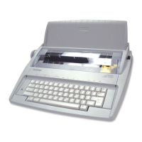
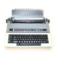
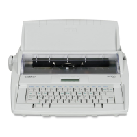
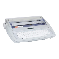
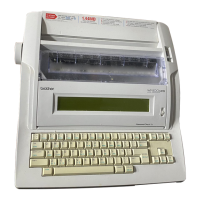
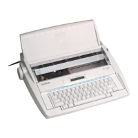
SERVICE MANUAL
iv
7.3.7. DISK TYPE ................................................................................................ 3-48
7.3.8. RS-232C Test ("Echo Back") ...................................................................... 3-49
CHAPTER 4 COMPONENT DISASSEMBLY............................................................. 4-1
1. Covers...................................................................................................................... 4-1
1.1. Upper Cover............................................................................................................... 4-2
1.1.1. Removing the Upper Cover .......................................................................... 4-2
1.1.2. Removing the Front Cover ........................................................................... 4-6
1.1.3. Installing the Upper Cover ............................................................................ 4-7
2. Keyboard Assembly ................................................................................................. 4-8
2.1. Removing the Keyboard............................................................................................. 4-8
2.2. Installing the Keyboard............................................................................................... 4-9
3. Ink Jet Printer Assembly......................................................................................... 4-10
3.1. Removing the Printer Assembly ............................................................................... 4-11
3.2. Installing the Printer Assembly.................................................................................. 4-11
3.3. Disassembling the Printer Assembly......................................................................... 4-12
3.3.1. Removing the CA Unit................................................................................ 4-13
3.3.2. Installing the CA Unit.................................................................................. 4-13
3.3.3. Disassembling the PF Unit.......................................................................... 4-14
3.3.3.1. Removing the Form.............................................................................. 4-15
3.3.3.2. Removing the Release Lever and Release Shaft.................................. 4-16
3.3.3.3. Removing the ACF Shaft Assembly...................................................... 4-17
3.3.3.4. Removing the Pressure Rollers and Roller Holders............................... 4-18
3.3.3.5. Removing the Holder Plate................................................................... 4-19
3.3.3.6. Removing the Hopper Assembly........................................................... 4-20
3.3.3.7. Disassembling the Paper Feed Assembly ............................................. 4-22
3.3.3.8. Removing the Eject Roller Assembly and the PF Roller Assembly........ 4-23
3.3.3.9. Removing the Motor Frame Assembly.................................................. 4-24
3.3.3.10. Removing the PF Stopper..................................................................... 4-25
3.3.3.11. Removing the PE Sensor...................................................................... 4-26
3.3.4. Disassembling the CA Unit ......................................................................... 4-27
3.3.4.1. Removing the Carriage......................................................................... 4-28
3.3.4.2. Removing the Carriage Drive................................................................ 4-30
3.3.4.3. Removing the Star Wheel Holder Assembly ......................................... 4-31
3.3.4.4. Removing the MS Holder Assembly...................................................... 4-32
3.3.4.5. Removing the Leaf Switch (Home Position Sensor) .............................. 4-33
3.3.4.6. Removing and Mounting the KB Switch Assy........................................ 4-34
3.4. Adjusting the CA Unit ............................................................................................... 4-35
3.4.1. Adjusting the Carriage Home Position......................................................... 4-35
3.4.2. Adjusting Belt Tension................................................................................ 4-36
 Loading...
