THEORY
Electrical
SERVICE MANUAL
2-20
9. LCD Module
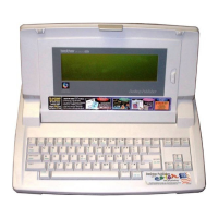
The block diagram of the LCD display operation is shown in Fig. 2.21. CBIC (#8) on the
main PCB outputs the LCD module control signals to the LCD module. The LCD drive
voltage (VEE) is generated by DC-DC convertor by the pulses output from CBIC (#8).
Display data, the data written to the SRAM (#6) that functions as Video RAM is always
sent to the LCD module as 4-bit parallel data.
Fig. 2.21 LCD Display Operation Block Diagram
 Loading...
