3-102
Confidential
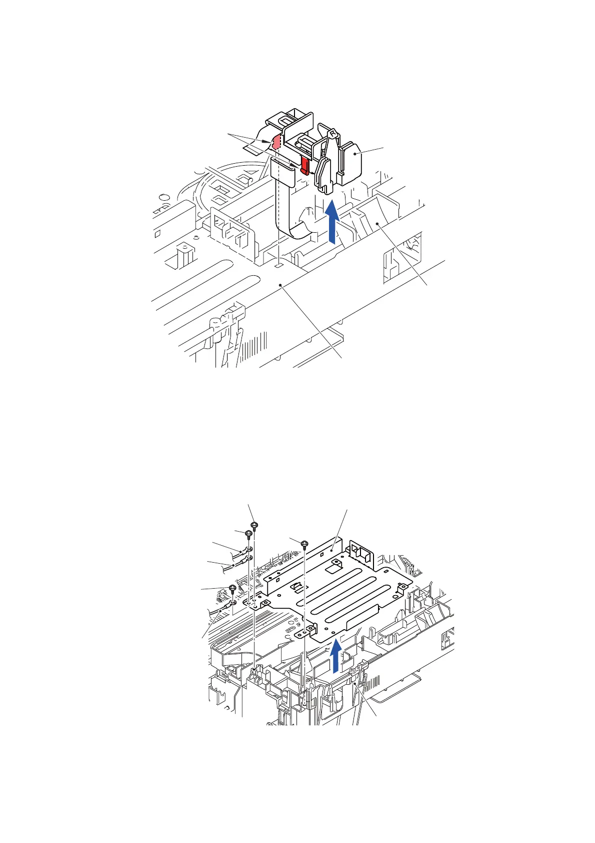
(8) Release the two Hooks and release the Main PCB harness hold R from the Main
PCB frame.
Fig. 3-121
(9) Remove the screw (SCREW BIND M3x6) and remove the T2 FG wire and PF FG
wire from the Main PCB frame.
(10)Remove the screw (SCREW BIND M3x6) and remove the Engine FG wire from the
Main PCB frame.
(11)Remove the two screws (SCREW CUP M3x6 and TAPTITE CUP B M3x10) and
remove the Main PCB frame from the Main body.
Fig. 3-122
Hooks
Main PCB harness hold R
Lower cover
Main PCB frame
T2 FG wire
PF FG wire
Main PCB frame
Engine FG wire
SCREW BIND M3x6
SCREW BIND M3x6
SCREW CUP M3x6
Main body
TAPTITE CUP B M3x10
 Loading...