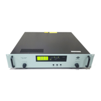
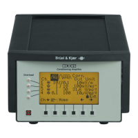
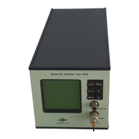
Measuring Ampifier Type 2525
User Manual Vol.1
1–5
BE1406–12
Chapter 1 –Introduction and Specifications
Specifications 2525
Relay: SPDT, Max. 48V, 0.5A
Alarm On/Off:
Selectable via LCD and Interface bus
Level:
Selectable over the entire dynamic range. Mon-
itoring will de-select while the autorange is
changing gain (missing time periods after gain
shifts)
Level Exceed Time:
Adjustable from 0 to 60s in steps of 1s
Alarm Hold Time:
Adjustable from 1 to 60s or infinite
Alarm Reset Function
Detector Type:
Selectable RMS, +Peak, –Peak, Peak-to-Peak.
Averaging/Hold time is transferred from detector
set-up. Detectors are sampled at 125ms inter-
vals (same interval as LCD meter digit updating)
DETECTOR DC OUTPUT:
In 15-pole D-Sub socket on rear
V/unit: equal to V/unit for AC output
Max Output: 3.5V (5 mA peak)
Output Impedance: 50Ω
DC Offset: <±5mV
Detector Type:
Selectable RMS, +Peak, –Peak, Peak-to-Peak.
Averaging/Hold time is transferred from detector
set-up
Sampling Frequency:
Output is updated at 125 ms intervals (same in-
terval as LCD meter digit updating). No curve
fitting on output
IEEE–488 INTERFACE:
The functions implemented conform to IEEE–
488.1 and IEC 625–1 standards. Any function
shown on display can be transmitted to and from
the apparatus
Functions Implemented:
Source Handshake SH1
Acceptor Handshake AH1
Talker T6
Listener L4
Device Clear DC1
Remote Local RL1
SERIAL INTERFACE:
Conforms to EIA/TIA–574 (“RS–232”)
Baud Rate: 2400, 4800, 9600
Parity: None
Data Bits: 8
Stop Bits: 1
Handshake:
X-On/X-Off, hardwired RTS/CTS, Modem DCD
Power Supply
Mains: 90V–127 V or 200 V–240 V; 24VA
Dimensions and Weight
Height: 132.5mm (5.22″)
Width: 139.5 mm (5.49″)
Depth: 320 mm (12.6″)
Weight: 3.6 kg (5.8 lb.)
Note: All values are typical unless measurement
uncertainty or tolerance field is specified.
COMPLIANCE WITH STANDARDS:
CE-mark indicates compliance with: EMC Directive and Low Voltage Directive.
Safety EN 61010–1 and IEC 1010–1: Safety requirements for electrical equipment for
measurement, control and laboratory use.
EMC Emission EN 50081–1: Generic emission standard. Part 1: Residential, commercial and
light industry.
EN 50081–2: Generic emission standard. Part 2: Industrial environment.
CISPR 22: Radio disturbance characteristics of information technology
equipment. Class B Limits.
FCC Rules, Part 15: Complies with the limits for a Class B digital device.
EMC Immunity EN 50082–1: Generic immunity standard. Part 1: Residential, commercial and
light industry.
EN 50082–2: Generic immunity standard. Part 2: Industrial environment.
Note 1: The above is guaranteed using accessories listed in this Product Data
sheet only.
Note 2: See “EMC”
Temperature IEC 68–2–1 & IEC68–2–2: Environmental Testing. Cold and Dry Heat.
Operating Temperature: 5 to 40°C (41 to 104°F)
Storage Temperature: –25 to +70°C (–13 to +158°F)
Humidity IEC 68–2–3: Damp Heat: 90% RH (non-condensing at 40°C (104°F))
Mechanical Non-operating:
IEC 68–2–6: Vibration: 0.3 mm, 20 m/s
2
, 10–500 Hz
IEC 68–2–27: Shock: 1000 m/s
2
IEC 68–2–29: Bump: 1000 bumps at 250 m/s
2
Enclosure IEC 529: Protection provided by enclosures: IP20
EMC
SUSCEPTIBILITY TO DISTURBANCES
SPECIFIED IN EN50082–2:
Measured using Accelerometer Cable AO 1382.
Charge floating measurements according to
User Manual with Ferrite Cable Clamp LK 0014
mounted on accelerometer cable.
At magnetic field 80 A/m charge input noise can
increase to 25fC
RADIATED RF: (3 to 10 V/m, 80% AM, 1kHz)
CONDUCTED RF: (3 to 10 V, 80% AM, 1kHz)
1
Measured with max. gain and 50 Ω AC termination
2
Measured with max. gain and 1nF termination
Input Radiated Conducted
DeltaTron
1
<0.6mV <20µV
Charge, single ended
2
<0.3pC <0.02pC
Charge, floating
2
<0.3pC <6pC
 Loading...
