Measuring Ampifier Type 2525
User Manual Vol.1
2–3
BE1406–12
Chapter 2 –Controls and Connections
Rear Panel
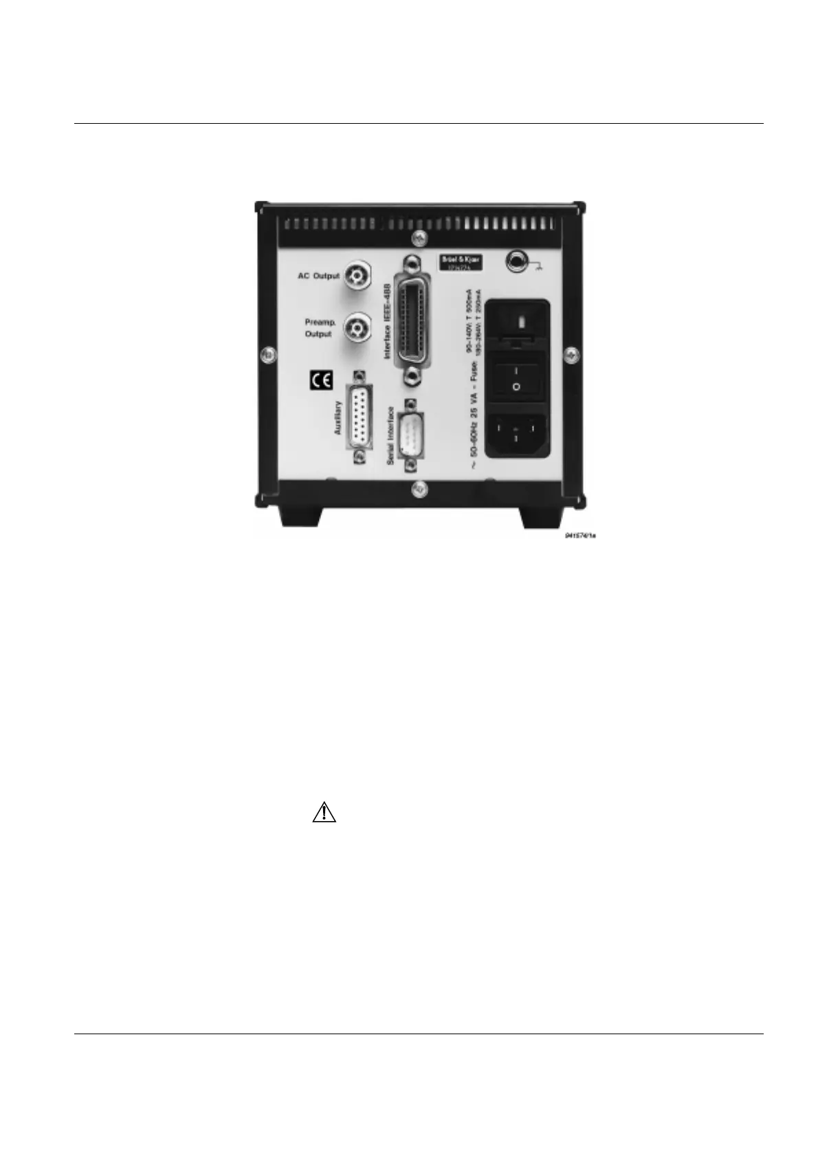
2.2 Rear Panel
Fig.2.2 Rear panel of Measuring Amplifier Type 2525
AC Output For connection of the processed signal to analyzers, recorders and
other measurement devices in the measurement chain after the
amplifier. See section 1.2 for full specification.
Preamp Output For connection to other instruments. The signal is taken just after
the 1st order high-pass filter and input and variable gain (see
Fig.2.3). See section 1.2 for full specification.
IEEE –488 Interface
Connector
24-pole socket for digital read-in/read-out from/to the controller of
measurement results and for remote control of the amplifier (see
separate interface manual) via the IEEE–488 interface.
WARNING: Switch off all equipment before connecting or
disconnecting the digital interface. Failure to do so could damage
the equipment.
Serial Interface
Connector
Serial interface socket for remote control and measurement re-
sults output of the amplifier (see separate interface manual).
Auxiliary Connector 15-pole connector for external filter attachment, alarm relay and
detector DC output (see Fig.2.4).

 Loading...


