Measuring Ampifier Type 2525
User Manual Vol.1
Brüel & Kjær
1–4
Chapter 1 –Introduction and Specifications
Specifications 2525
1.2 Specifications 2525
CHARGE INPUT:
Floating or grounded via TNC socket on front
Max. Input 0 to 100 kHz: 50nC peak
Max. Common Mode Voltage on Floating Input:
5Vpeak at charge input level max. 10nCpeak
Common Mode Rejection Ratio (CMRR):
With input gain +20 to +60 dB:
100Hz CMRR >60dB
10 kHz CMRR >45 dB
With input gain –20 to +10dB:
100Hz CMRR >50dB
10 kHz CMRR >40 dB
Total Sensitivity:
0.1 pC to 10nC in steps of 10 dB for 1 V on
AC output
0.03 pC to 10nC in steps of 0.01 dB step for
1V on AC output, with reduced frequency
range
Gain:
Input Gain (before filtering and integration):
Selectable from –20dB to +60dB in steps of
10dB
Variable Gain (before filtering and integration):
Selectable from 0dB to 11dB in steps of 0.01dB
Output Gain (after filtering and integration):
Selectable 0dB, 10dB and 20dB
Inherent Noise 2 Hz to 22 kHz
Single-ended: <5fC (<7 fC @ 90% RH)
Floating: <10fC
on AC output, referred to input with maximum
sensitivity, Lower Frequency Limit = 1 Hz, and
1 nF transducer capacitance
Gain Accuracy (from input to AC output at
1kHz):
Acceleration and force: Better than 2%
Velocity: Better than 2.5%
Displacement: Better than 3.0% @ 100 Hz
DeltaTron
INPUT:
Via BNC socket on front
Sensitivity:
100 µV to 10V in steps of 10dB for 1V on
AC output
30 µV to 10 V in steps of 0.01 dB for 1 V on
AC output, with reduced frequency range
Gain:
Input Gain (before filtering and integration):
Selectable from –20 dB to +60dB in steps of
10 dB
Variable Gain (before filtering and integration):
Selectable from 0 dB to 11dB in steps of
0.01 dB
Output Gain (after filtering and integration):
Selectable 0dB, 10 dB, 20dB
Gain Accuracy:
Acceleration and force: Better than 2%
Velocity: Better than 2.5%
Displacement: Better than 3.0%
Inherent Noise 2 Hz to 22 kHz:
<20µV referred to input with maximum sen-
sitivity and transducer output impedance
<1kΩ
Input Impedance: >100kΩ
Power Supply for DeltaTron
Accelerometer:
Constant Current: 4mA.
Max Voltage on DeltaTron
input: 27V
Out-of-range detection on DeltaTron
supply
voltage (<3V or >21V)
PREAMP OUTPUT:
BNC socket on rear
Acceleration signal after 1st order high-pass fil-
ter, input gain and variable gain
Max. Output: 5V peak (5mA peak)
Output Impedance: 50 Ω
DC Offset: –50 <offset <+50mV
AC OUTPUT:
Via BNC socket on rear
Fully conditioned signal
Max. Output: 5V peak (5mA peak)
Output Impedance: 50 Ω
DC Offset: –10 <offset <+10mV
FREQUENCY RANGE:
Acceleration & Force:
0.2Hz (better than –10% limit) to 100 kHz (better
than –20% limit)
With variable gain selected: 0.2 Hz to 40 kHz
(better than –10% limit)
Velocity:
1 Hz to 10kHz (better than ±10% limits)
Displacement:
1Hz to 1kHz (better than ±10% limits)
LOW-PASS FILTERS:
2-pole Butterworth (maximally flat)
Selectable –3dB limits of 1, 3, 10, 30kHz and OFF
Filter Slope: 40 dB/decade
Accuracy on –3 dB Limit Freq.: ±5%, re 1kHz
without filter
HIGH-PASS FILTERS:
3-pole Butterworth (maximally flat)
Selectable –3 dB limits of 0.1, 0.3, 1, 3, 10, 30 Hz
and OFF
Filter Slope: 60 dB/decade
Accuracy on –3 dB Limit Freq.: ±10% (3, 10,
30 Hz), +10/−15% (0.1, 0.3, 1 Hz), re 1kHz with-
out filter
ADDITIONAL FILTERS:
External filter connection via 15-pole D-sub-con-
nector on rear.
Optional custom internal filtering available on re-
quest.
External filter serially connected to standard fil-
ters
DISTORTION:
<0.12% to 10kHz, <1% to 100kHz
TEST OSCILLATOR:
159.2Hz (= 1000 rad/s), 100 pC sinusoidal, ±1%
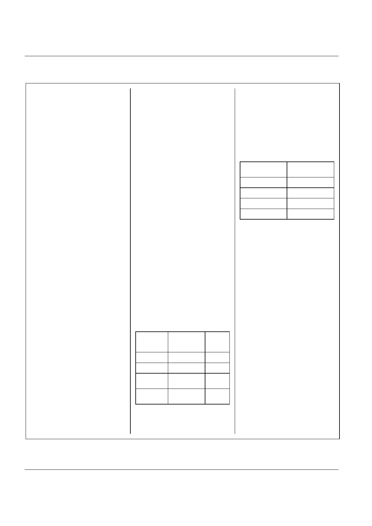
SIGNAL RMS DECTECTOR:
Accuracy for crest factor <3:
Averaging Time:
Exponential: 125ms, 1s, 10s
Linear: 1s or 60s based on 125 ms exp. val-
ues
SIGNAL PEAK DETECTOR:
+Peak, –Peak:
Settling time for a level shift from 0 to 3 V on
AC output:
56 µs (to –10% of value)
72 µs (to –5% of value)
94 µs (to –2% of value)
Read-out (at AC output) value for a 3 V peak
of a period of one half sine with a (full period)
frequency as listed:
Max Peak Hold Time:
0.5s to 60s in steps of 0.5 s or infinite
Max peak reset function
Dynamic range:
+30mV to 3V on AC output (40dB)
Peak-to-Peak:
The numerical sum of +peak and –peak with
extra hold time as described above
OVERLOADS:
Signal Overload:
Peak overloading internal circuits
Upper 20dB:
Indicates that at least one internal circuit is op-
erating less than 20dB from overload
CM Overload:
Common mode peak voltage >5 V at floating
charge input
DeltaTron
Overload:
DeltaTron
supply voltage <3.0 V or >21.0 V
GAIN AUTORANGE:
None (manual gain setting)
On output gain only
On input and output gain
OVERLOAD RECOVERY TIME: <200 µs
Time for output to recover to within 250mV of
the original value after termination of a half sine
pulse of 50µs duration at the baseline. Pulse
amplitude is 4 times the full scale input, peak
ACCELEROMETER MOUNTED RESONANCE
MEASURING (patent pending):
Done via pulse method measuring. Exciting
pulse ±15 V, 3 kHz to 60kHz
Can be used with a number of Brüel & Kjær
Charge Accelerometers
EXTERNAL FILTER:
Connected between the internal filters and the
output gain
ALARM FUNCTION:
Level monitoring with alarm output
Alarm Output:
In the 15-pole D-Sub socket on rear of amplifier
Freq. Range
Dynamic range
referred to 1V
on AC output
Accuracy
referred
to input**
1 Hz to 10 kHz +10dB to –30dB* ±5%
1 Hz to 30 kHz +10dB to –30dB* ±10%
1Hz to 100 kHz +10dB to –20dB
+10%
–25%
1Hz to 100 kHz +10dB to –10dB
+5%
–20%
For 60s linear averaging:
* the dynamic range is +10 to −20 dB
** 10% must be subtracted from the negative
accuracy value (e.g. +5%, −15%, etc.)
Sine Frequency
Read-out
(% of FS peak value)
1.0kHz –2%
2.5kHz –8%
5.0kHz –20%
10.0 kHz –40%

 Loading...


